
Detection and fabrication of diamagnetically levitated disk
We magnetically levitate a diamagnetic, conductive pyrolytic graphite (PG) disk within an axisymmetric magnetic trap, as illustrated in Fig. 1. The trap consists of five layers of ring-shaped NdFeB magnets (OD 19 × ID 8.1 × H 4 mm; N40) and two layers of cylindrical NdFeB magnets (D 8 × H 10 mm; N52), arranged with alternating magnetization for radial trapping. Due to its strong diamagnetic properties at room temperature, the PG disk achieves stable macroscopic levitation using commercial permanent magnets. The disk (diameter D = 10.02 mm, height H = 1.12 mm) was precisely fabricated from a PG plate via computer numerical control (CNC) machining, followed by diamond polishing to ensure high circularity. Further fabrication details are provided in the Methods: PG disk fabrication process.
Fig. 1: Diamagnetic levitation and rotation of a pyrolytic graphite (PG) disk in an axially symmetric magnetic trap.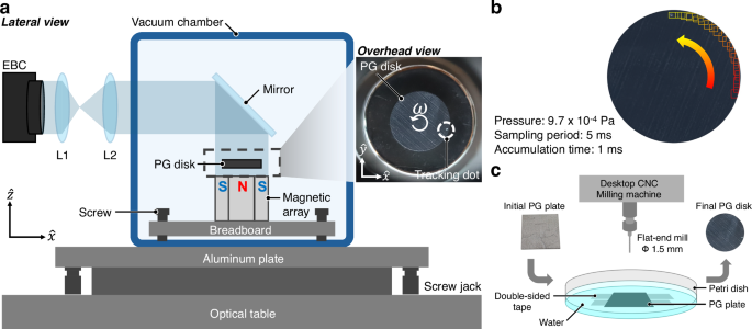
a Lateral view of the levitation setup. An axially symmetric magnetic array, consisting of cylindrical and surrounding ring magnets arranged with alternating vertical magnetization, levitates a PG disk. The magnets are fixed to a breadboard, whose initial inclination is adjusted to be as horizontal as possible using screws inside the vacuum chamber (reaching P ~ 5 × 10⁻⁵ Pa). The chamber itself is mounted on an aluminum plate atop an optical table, with its inclination adjusted away from the horizontal using the optical table and screw jacks. The top surface of the levitating disk is viewed via a flat mirror and two convex lenses (L1, L2), forming a Keplerian telescope for magnification, and its motion is tracked using an event-based camera (EBC). The inset shows a photograph of the levitated PG disk, marked with a white ink dot for orientation. b EBC [Prophesee EVK-V3HD], detections of the tracking dot on the rotating PG disk. Twenty consecutive detections (squares) are shown for illustration. c Schematic of the PG disk fabrication. A square PG plate (3 cm sidelength) is roughly milled using a desktop CNC machine [SnapMaker]. It is secured in a Petri dish half-filled with water, which disperses cut material, cools the disk, and eliminates dust formation. The disk is then precisely shaped and polished using a lapidary faceting machine [Ultratec V5], producing the final 10 mm diameter PG disk (right image).
The rotation of the disk was measured using an event-based camera (EBC), which detects local brightness changes. To facilitate tracking, a small white ink dot was applied to the top surface of the disk, as shown in the overhead view of Fig. 1a. The EBC extracted the dot’s center coordinates using a built-in motion-tracking algorithm, enabling the determination of the disk’s kinematics. Figure 1b shows an example of twenty tracked dot positions over 100 ms. The disk’s top surface was viewed via a 45°-angled flat mirror assisted by two convex lenses, L1 and L2, with corresponding focal lengths of f1 = 3 mm and f2 = 12 mm, forming a Keplerian telescope for magnification.
To analyze the rotational dynamics of the levitated disk, we define the rotational damping rate γ [Hz], which characterizes the exponential decay of the angular velocity ω(t):
$$\omega (t)={\omega }_{0}{e}^{-\gamma t},$$
where ω0 = ω(t = 0) is the initial angular velocity. The exponentially decaying dynamics arise when the damping torque is viscous, meaning it is linearly proportional to the angular velocity:
$${{{\mathcal{T}}}}=-\varGamma \omega ,$$
where Γ = γI is the rotational damping coefficient, and \(I=\frac{1}{2}M{R}^{2}\) is the moment of inertia of a uniform disk (mass M, radius R), about an axis of rotation passing through the center of the disk, perpendicular to the plane of the disk. The negative sign indicates that the torque acts to damp the rotation. In our experiment, the assumption of viscous damping holds accurately, as evidenced by the linear relationship:
$$\frac{d}{dt}\ln \omega (t)\propto -{{{\rm{const}}}}.$$
Pressure dependence of rotational damping
Gas friction damping is one of the major motional damping sources caused by the collision between the gas molecules and the object, and is dependent on the gas pressure. To distinguish gas friction damping from other rotational damping mechanisms, we first characterize the pressure dependence of the disk’s rotational damping rate γ.
We determine the rotational damping rate γ by monitoring the decay of the disk’s angular velocity ω using the EBC. Rotation was induced by lateral vibrational excitations of the setup along the x-and y-axes. This produced both rotational and translational motions, though the latter damped out rapidly. The angular velocity ω(t) was extracted from the disk’s orientation ϕ(t), detected by the EBC. In Fig. 2a, b, we plot the decay curve of ω(t) at two typical pressures, 1.0 × 10⁵ Pa and 5.3 × 10⁻⁵ Pa, respectively. The angular speed exhibits clear exponential decay, and γ is obtained from the slope of the linear fit of ln(ω). The fit to exponential decay is very clear and over a large time span. The obtained damping rates at different pressures are plotted in Fig. 2c. At high pressure, γ remains nearly constant, while in the intermediate pressure range, it scales linearly with pressure. At low pressure, γ reaches a plateau.
Fig. 2: Spin-down of an initially rotating levitated disk.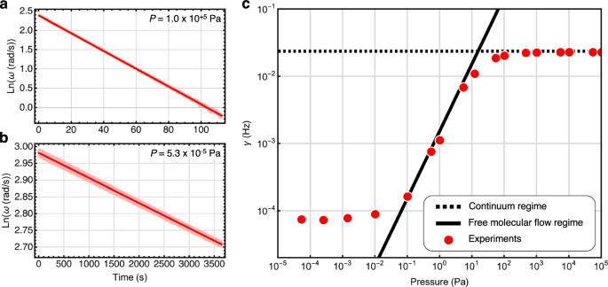
The disk is first spun up using an applied torque. Once it reaches a sufficiently high angular velocity ω, the torque is removed, and its spin-down is monitored over time. a, b Experimentally measured values of \(\ln (\omega )\) as a function of time for high and low gas pressures P, along with best-fit lines whose slopes correspond to γ(P). The data closely follow \(\omega (t)={\omega }_{0}\exp (-\gamma t)\), indicating that angular velocity damping is well-approximated by viscous drag. c Rotational damping rate γ(P) as a function of gas pressure P for a fixed, non-zero inclination of supporting platform. The horizontal dashed line represents the damping rate estimated via FEM-COMSOL simulation in the high-pressure regime, where the continuum assumption of fluid dynamics holds. The diagonal solid line represents the theoretical prediction of γ(P) in the free molecular flow regime36. The experimentally determined values of γ(P) from spin-down measurements are shown as red circles. The associated error, obtained from the error in the linear fit, is smaller than the marker size. For P < 10−1 Pa, a plateau in γ(P) suggests a dominant damping mechanism beyond gas friction, likely eddy damping due to deviations from perfectly axial symmetry. Potential sources include material imperfections in the disk or magnets, or a slight inclination of the setup, shifting the PG disk’s center of mass off-axis.
The interaction mechanism between gas molecules and an object strongly depends on the ratio between the gas molecule’s mean free path λ and the size of the object of interest H, which is known as the Knudsen number, Kn = λ/H. At high pressure (P > 103 Pa), where Kn < 0.01, gas behaves as a continuous fluid and follows the principles of classical fluid dynamics, a regime known as continuum flow. As pressure decreases (100 Pa < P < 103 Pa), the system enters a transition regime where the gas flow gradually shifts from continuum behavior to free molecular flow. At low pressure (P < 100 Pa), where Kn > 10, intermolecular collisions become negligible, and gas molecules move ballistically, defining the free molecular flow regime.
We developed an FEM model to simulate the rotational gas friction damping of a levitated disk in the continuum flow regime. Under these conditions, airflow can be well-behaved and laminar, chaotic and turbulent, or in a transitional state between these extremes, depending largely on flow velocity. Our experiments apply to the laminar flow regime as the angular velocity of the rotating disk is very low. COMSOL’s laminar flow module was used to model this behavior. Figure 3a depicts a cross-sectional view of the simulated laminar flow generated by a rotating disk at ω = 2π × 2 rad s−1 under ambient conditions. At z = 0 mm, a no-slip boundary condition is applied to simulate the presence of the top surface of the magnetic array. The color density shows the velocity magnitude of the flow, whereas the streamline shows the direction of the axial flow. By integrating the airflow-induced shear stress over the disk’s surface, we obtain the total rotational gas friction torque \(| {{{\mathcal{T}}}}(\omega )| =\Gamma \omega =\gamma I\omega\), as a function of ω at a specific pressure, as shown in Fig. 3b. The slope of the linear fit corresponds to Γ = γI. The simulated damping rate γ at different pressures is plotted as blue circles, as shown in Fig. 3c. The simulation agrees well with the experimental data in the continuum flow regime at high pressures P > 102 Pa (unshaded region). In this regime, the rotational damping rate changes slightly with pressure. Refer to the Methods for further details on the COMSOL modeling.
Fig. 3: Simulation of rotational damping in the continuum flow regime (high pressure).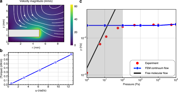
A finite element method (FEM) COMSOL fluid dynamic model is developed to predict rotational damping in the regime where the continuum approximation for the gas dynamics holds. a Cross-sectional view of the simulated laminar flow around a rotating disk (gray rectangle) with perfect coaxial symmetry. The disk rotates about its vertical axis r = 0 at ω = 2π × 2 rad s−1 within a cylindrical gas-filled tank in the continuum regime. Sliding wall boundary conditions are applied to the disk surfaces. Contours and arrows indicate axial flow, while the colormap represents the magnitude of total (axial and azimuthal) flow. b Dependence of the angular damping torque \(| {{{\mathcal{T}}}}|\) on the disk for various angular velocities ω (light blue circles) at P ~ 105 Pa, along with the best-fit line (blue). The slope of this line corresponds to Γ(P) = γ(P)I. c Comparison of experimental data (red) and FEM simulation results (blue) at high pressure, with no fitted parameters. The associated error for the simulation results, obtained from the error in the linear fit, is smaller than the marker size. The simulation aligns well with experimental data at high pressures (unshaded region) but deviates for P ≤ 102 Pa (shaded region), where the continuum approximation begins to break down. The solid black line represents the theoretical estimate for γ(P) in the molecular flow regime.
In the free molecular flow regime, the damping coefficient of the rotational motion of a disk is linearly proportional to the pressure P36,
$${\varGamma }_{{{{\rm{fm}}}}}(P)=\sigma {R}^{4}\sqrt{\frac{\pi {m}_{0}}{2{k}_{{{{\rm{B}}}}}T}}\left(1+\frac{2H}{R}\right)P,$$
where σ is a dimensionless accommodation factor, m0 is the mass of the gas molecule, T is the temperature of the surrounding environment, and R and H are the radii and thickness of the disk, respectively. The accommodation factor σ describes the surface effects, and we use σ = 1 for our polished-surface sample. We analytically obtain the rotational damping rate in the free molecular flow regime as γfm(P) = Γfm(P)/I. As shown in Fig. 2c, the analytical prediction matches well with the experimental data in the range of 10−1 Pa < P < 5 × 100 Pa, which is the free molecule flow regime, implying negligible surface effects and squeezed-film-like effects in our setup. However, the experimental data reach a plateau at lower pressure, suggesting that other forms of damping dominate the gas molecule damping at very low pressure.
Rotational eddy damping via tilt-induced symmetry breaking
When the axially symmetric levitation setup is placed on a platform that has a slight inclination to the horizontal, the center of mass (COM) of the levitated disk is displaced laterally due to gravity, leading to the breaking of axial symmetry. In such a situation, we expect there to be small eddy damping associated with the broken axial symmetry of the disk’s rotation. To explain the plateau in the rotational damping in the low-pressure region (see Fig. 2c), we study the dependence of the rotational damping rate on small tilting angles.
To investigate the effect of the small tilt, we keep the pressure constant P ~ 4.85 (±0.25) × 10−5 Pa, which is within the low-pressure plateau regime. As depicted in Fig. 1, the vacuum chamber containing the experimental setup sits on a thick aluminum plate, which itself sits on an optical table. We controlled the tilt of the setup in 2D, characterized by small tilt angles about the x-, y- axes, θx and θy, via adjustments of the nitrogen flow level of the optical table legs (coarse tuning) and using screw jacks (fine tuning). We then measured the rotational damping rate γ(θx, θy) at various two-dimensional inclinations of the platform \(({\theta }_{x}^{i},{\theta }_{y}^{j})\), as shown in Fig. 4c. Red circles and blue squares indicate a separate tilt sequence \(({\theta }_{x}^{i},{\theta }_{y}^{j})\), and their measured values of γ, and a fitted 2D contour plot. We observed that the minimum damping was evidenced at a non-zero 2D tilt \({\theta }_{x}^{\min },{\theta }_{y}^{\min }\,\ne \,(0,0)\), which corresponds to the orientation at which gravity is perpendicular to the top of the magnet array inside the chamber (i.e., the “true absolute level”). This offset is due to a slight misalignment of the inclination of the platform inside the vacuum chamber (further discussed in the Methods: Inclination angle measurement). From this minimum value, γ shows a steep increase by an order of magnitude within Δθ ~ 0.5°, showing a clear tilt angle dependence of γ.
Fig. 4: Studying the dependence of rotational damping rate γ on the inclination of the plate to the horizontal: γ(θx, θy).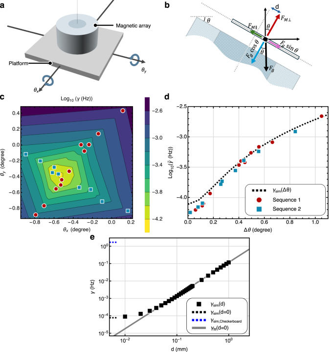
As the setup tilts, the center of mass (COM) of the PG disk shifts off axial symmetry, increasing eddy damping. a Tilting of the supporting platform by angles (θx, θy), about the (x, y) axes. b Force diagram of the levitated disk’s COM. The PG disk is trapped by a balance of perpendicular forces: \({F}_{{{{\rm{M\perp }}}}}={F}_{{{{\rm{g}}}}}\cos \theta\), and lateral forces: \({F}_{{{{\rm{M\parallel }}}}} \sim m{\omega }_{{{{\rm{L}}}}}^{2}\,d={F}_{{{{\rm{g}}}}}\sin \theta\), where ωL is the lateral oscillation frequency of the PG plate, and d is the lateral COM displacement from the axis of symmetry of the magnets, which increases with θ. c Measured dependence of γ(θx, θy). Red circles and blue squares indicate two measurement sequences, showing \(\min \gamma ({\theta }_{x},{\theta }_{y})\) at \(({\theta }_{x},{\theta }_{y})=({\theta }_{x}^{0},{\theta }_{y}^{0})\,\ne \,(0,0)\) due to a small initial misalignment. The associated error (SE) is smaller than the marker size. d Radial fit to \(\gamma (\delta {\theta }_{x}+{\theta }_{x}^{0},\delta {\theta }_{y}+{\theta }_{y}^{0})\equiv \tilde{\gamma }(\Delta \theta )\), where \(\Delta {\theta }^{2}=\delta {\theta }_{x}^{2}+\delta {\theta }_{y}^{2}\), yielding a 1D collapsed plot of the 2D data from c. The associated vertical and horizontal errors for the measurements, obtained from the error in the linear fit and SE, are smaller than the marker size. The dashed curve is a FEM-COMSOL estimate assuming only eddy damping, matching experiments for Δθ > 0.1° but breaking down for Δθ < 0.1° (see e). e Numerical FEM study of γ(d). From symmetry arguments, we expect γ(d → 0) → 0, but due to the non-axially symmetric nature of the FEM mesh and numerical errors, the simulation yields γ(d → 0) ≠ 0. For d > 0.05 mm, simulations show a near-perfect power-law dependence (Eq. (2)), supporting γ(d = 0) = 0 for perfect axial symmetry.
We fitted the two-dimensional damping rate γ(θx, θy) function to a one-dimensional damping rate \(\tilde{\gamma }(\Delta \theta )\), assuming that the damping rate is axially symmetric about the minimum (\({\theta }_{x}^{\min },{\theta }_{y}^{\min }\)), and is only a function of the tilt angle away from this minimum location. We plot \(\tilde{\gamma }(\Delta \theta )\), in Fig. 4d, and observe that all the data fits well onto a smooth curve, justifying the assumption of axial symmetry in tilt for γ. We compare this experimental data with simulated results obtained via FEM, represented by the black dashed curve. The FEM simulation models the eddy damping force due to the off-axis rotation of the disk. To perform this simulation, one requires estimates for the values of various material properties, such as the magnetic susceptibilities of the graphite. The diamagnetic susceptibilities in the horizontal and vertical directions in the graphite are estimated to match the measured horizontal and vertical oscillation frequencies of the disk and the measured levitation height, given the strength of the magnet arrays. Using the force diagram depicted in Fig. 4b, we obtain a relationship between the tilt angle of the platform, Δθ, and the displacement of the center of mass of the levitated disk from the axis of axial symmetry, d.
$$d(\Delta \theta )=g\Delta \theta /{\omega }_{{{{\rm{L}}}}}^{2}$$
(1)
where g is the gravitational acceleration. In the above relation, a small-angle approximation is also used, and its experimental validation is discussed in the Methods: Tilt-horizontal displacement relation. As we work in the small-angle regime, the relative tilting of the levitated disk with respect to the top surface of the magnetic array is also neglected. The FEM simulation of the resulting off-axis rotational eddy-damping also requires values for the in-plane S∥ and perpendicular S⊥ electrical conductance of the disk. We find that γ is insensitive to S⊥, and we are thus left with one fitting parameter S∥, whose fitted value is shown in Table 1. The simulated damping matches well with experimental results for Δθ > 0.1°.
Table 1 Parameters used in the rotational eddy damping simulations
On the other hand, the 3D FEM simulations become unreliable below Δθ < 0.1°. In Fig. 4e, we plot the simulated damping \({\gamma }_{{{{\rm{sim}}}}}(d)\) as black squares and its zero-displacement limit \({\gamma }_{{{{\rm{sim}}}}}(0)\) as a dashed line. Although perfect axial symmetry demands γ(d → 0) = 0, the nonzero damping here stems from mesh-induced asymmetry and numerical error (see Supplementary Material). To bypass these artifacts, we fit the region d > 0.05 mm to a power law,
$${\gamma }_{{{{\rm{fit}}}}}(d)={c}_{1}{d}^{{c}_{2}},\quad {c}_{1}=6.20\times 1{0}^{4},\quad {c}_{2}=1.91,$$
(2)
shown as the gray line. The near-perfect power-law dependence strongly supports γ(d = 0) = 0 under ideal symmetry.
When the setup gets close to the axially symmetric conditions, the damping rate drops dramatically, and the errors in the FEM simulations dominate, leading to a non-zero damping plateau (as shown in Fig. 4d, e). We then build a 2D axisymmetric FEM model to simulate the eddy damping, which will eliminate the error caused by the asymmetric mesh. The results show a lower damping rate of γ ~ 4 × 10⁻⁶ Hz, which is still far from zero, which is due to numerical errors in the FEM simulation (See Supplementary Note 1). To confirm this, we next present analytical proofs and a demonstration that shows that in the case of perfect axial symmetry, J = 0.
Analytical demonstration of vanishing current in an ideal symmetry
We now analytically prove that the steady-state current density J inside an axially symmetric rigidly rotating conductor, rotating co-axially in an axially symmetric magnetic field, is zero for the entire volume. We consider an axisymmetric field
$${{{\bf{B}}}}(r,z)={B}_{r}(r,z)\,\hat{r}+{B}_{z}(r,z)\,\hat{z},\quad \nabla \cdot {{{\bf{B}}}}=\frac{1}{r}{\partial }_{r}(r{B}_{r})+{\partial }_{z}{B}_{z}=0.$$
For a conductor with rigid rotation, \({{{\bf{v}}}}=\omega r\,\hat{\phi }\), the current density expression is:
$${{{\bf{J}}}}=\sigma (-\nabla V+{{{\bf{v}}}}\times {{{\bf{B}}}}),\quad {{{\bf{v}}}}\times {{{\bf{B}}}}={v}_{\phi }{B}_{z}\,\hat{r}-{v}_{\phi }{B}_{r}\,\hat{z}.$$
Using ∇ × (fA) = ∇f × A + f ∇ × A, we get
$$\nabla \times {{{\bf{J}}}} =\nabla \times (-\sigma \nabla V+\sigma ({{{\bf{v}}}}\times {{{\bf{B}}}}))\\ =-(\nabla \sigma \times \nabla V)-\sigma (\nabla \times \nabla V)+\nabla \sigma \times ({{{\bf{v}}}}\times {{{\bf{B}}}})+\sigma \,\nabla \times ({{{\bf{v}}}}\times {{{\bf{B}}}})\\ =\nabla \sigma \times [-\nabla V+({{{\bf{v}}}}\times {{{\bf{B}}}})]-\sigma (\nabla \times \nabla V)+\sigma \,\nabla \times ({{{\bf{v}}}}\times {{{\bf{B}}}}).$$
Enforcing ∇σ = 0 for a uniform conductivity and noting ∇ × ∇ V = 0, only the last term remains:
$$\nabla \times {{{\bf{J}}}}=\sigma \,\nabla \times ({{{\bf{v}}}}\times {{{\bf{B}}}}).$$
But
$$\nabla \times ({{{\bf{v}}}}\times {{{\bf{B}}}})=\omega r\left({\partial }_{z}{B}_{z}+\frac{1}{r}{\partial }_{r}(r{B}_{r})\right)=\omega r\,\nabla \,\cdot \,{{{\bf{B}}}}=0.$$
Hence ∇ × J = 0 for a rotating conductor in an axially symmetric magnetic field. This now implies that there cannot be any closed current loops within the conductor, e.g., eddy currents. However, we can go further and show that J = 0.
Since ∇ × J = 0, there exists a scalar potential Φ such that J = ∇ Φ. The steady-state continuity and boundary conditions for the current satisfy
$$\nabla \cdot {{{\bf{J}}}}=0,\quad {{{\bf{J}}}}\cdot \hat{n}{| }_{S}=0\quad \Rightarrow \quad {\nabla }^{2}\varPhi =0,\quad \nabla \varPhi \cdot \hat{n}{| }_{S}=0.$$
Using the above conditions and Green’s first identity, we show that
$${\int}_{V}{\left\vert \nabla \varPhi \right\vert }^{2}\ dV={\int}_{S}\varPhi \left(\nabla \varPhi \cdot \hat{n}\right)dS-{\int}_{V}\varPhi {\nabla }^{2}\varPhi dV=0.$$
This implies that ∇ Φ = 0 everywhere in V, and therefore,
$${{{\bf{J}}}}=\nabla \varPhi =0\quad {{{\rm{through}}}}\,{{{\rm{out}}}}\,{{{\rm{the}}}}\,{{{\rm{conductor}}}}.$$
Following the proof, we demonstrate an explicit calculation of an example in which a rotating conductor carries no steady–state current. Guided by the oscillatory radial components, we define an axisymmetric magnetic field that is divergence–free by construction:
$${B}_{r}(r)=\beta \sin \alpha r,\quad {B}_{z}(r,z)=-\beta (z+{z}_{0})\left(\frac{\sin (\alpha r)}{r}+\alpha \cos (\alpha r)\right).$$
(3)
As shown in Fig. 5, the vector components of the field (with α = π/6, β = 0.1, z0 = −4) closely replicate those of the magnetic field generated from an axially symmetric magnetic array.
Fig. 5: Comparison between the simulated magnetic field generated by a typical axially symmetric magnetic array and the analytical example.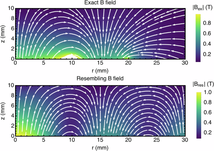
The simulated magnetic field Bex is calculated with an exact analytical expression45 with the parameters listed in the Tables 1 and 2. The analytical resembling magnetic field, \({{{{\bf{B}}}}}_{{{{\rm{res}}}}}={B}_{r}(r)\hspace{1.111pt}\hat{r}+{B}_{z}(r,z)\hspace{1.111pt}\hat{z}\), is built from Eq. (3), with α = π/6, β = 0.1, and z0 = −4.
Assuming for this example isotropic conductivity σ and rigid rotation about the axis, \({{{\bf{v}}}}=\omega r\hat{\phi }\), we calculate that
$${{{\bf{v}}}}\times {{{\bf{B}}}}=-\omega z(\sin (\alpha r)+\alpha r\cos (\alpha r))\hat{r}-\omega z\sin (\alpha r)\hat{z}.$$
Using this, we obtain the continuity equation to be
$${\nabla }^{2}V=\nabla \cdot \left({{{\bf{v}}}}\times {{{\bf{B}}}}\right)=-\omega z\left(\frac{\sin (\alpha r)}{r}+3\alpha \cos (\alpha r)-{\alpha }^{2}r\sin (\alpha r)\right).$$
We then seek V(r, z) satisfying this Poisson equation and Jr(r = 0, R) = Jz(z = ± H/2) = 0. A direct check shows that the ansatz
$$V(r,z)=-\omega rz\sin (\alpha r)$$
both solves \({\nabla }^{2}V=\nabla \cdot \left({{{\bf{v}}}}\times {{{\bf{B}}}}\right)\) and enforces \({{{\bf{J}}}}\cdot \hat{n}=0\) on all boundaries. Substituting into the current density expression, we obtain that
$${{{\bf{J}}}}(r,z)=0\,{{{\rm{for}}}}\,{{{\rm{all}}}}\,0\le r\le R\,{{{\rm{and}}}}-\frac{H}{2}\le z\le \frac{H}{2}.$$
Thus, even in the presence of rotation and a nontrivial magnetic geometry, no bulk currents circulate. This analytic result validates our FEM simulations and confirms that there is no eddy damping for a conductive disk rotating with a constant angular velocity in an ideally axially symmetric magnetic field. We thank the reviewer for bringing references37,38,39 to our attention, which also include a proof.
Possible origin of residual damping
While ideal axial symmetry predicts zero eddy damping, our experiments reveal a residual rate of \({\gamma }_{\min }=5.5\times 1{0}^{-5}{{{\rm{Hz}}}}\) equivalent to a static symmetry-breaking offset of d ≈ 18 μm (Eq. (2)). Side-view video shows the slight wobbling of the disk, which in fact reflects the disk’s center of mass tracing a small circle around the trap axis at a fixed offset, equivalent to a static tilt that generates eddy-current damping (Supplementary Movie 3). Such an offset may arise from slight geometric or material asymmetries in either the pyrolytic graphite disk or the magnet assembly. For example, lateral variations in conductivity or diamagnetic susceptibility may be present due to misalignment between the disk’s geometric axis and the graphite c-axis. Indeed, when the disk is levitated on the checkerboard magnet array, the disk has a preferential orientation with librational confinement, signaling an internal asymmetry (see Supplementary Movie 1). Other possible sources of damping, such as surface-localized currents from the skin effect at high angular velocities in an inhomogeneous electromagnetic environment, were examined in Supplementary Note 3 and found to be negligible in our setup.
Dynamical symmetry breaking from thermal fluctuations or environmental vibrations can displace the disk off-center, inducing eddy-current damping even with perfect static tilt control. To quantify the damping rate arising from thermal fluctuations at ambient temperature, we estimate the root-mean-square displacement via the equipartition theorem, \({x}_{{{{\rm{rms}}}}}=\sqrt{{k}_{{{{\rm{B}}}}}T/m{\omega}^{2}}\approx 1.2\times 1{0}^{-10}\ {{{\rm{m}}}}\) for T = 300 K, m = 191 mg, and ω/2π = 6 Hz. Substitution into Eq. (2) yields a thermal noise-induced damping rate of ~7 × 10⁻¹⁵ Hz, about ten orders of magnitude below our measured \({\gamma }_{\min }\). Moreover, gyroscopic stabilization at higher angular velocity further suppresses any residual eddy currents due to transverse motion. We therefore conclude that static imperfections dominate the observed residual damping.