
Creation of topological monopole-antimonopole pairs in half skyrmions
Topological defects, which are a necessary result of broken continuous symmetry, can be observed in the liquid crystal system employing a heating-cooling phase transition51. To create topologically protected skyrmion strings, a nematic LC slab with geometric frustration by different topological patterns is prepared. The bottom substrate is of alternating splay-bend distortions with director field designed as \(\hat{{{{\bf{n}}}}}=({n}_{x},{n}_{y},{n}_{z})=(\cos \alpha,\sin \alpha,0)\), where \(\alpha=\pi x/L\), L = 100 μm is the period, and the top surface is of uniform alignment along the y-axis, (Fig. 1a and Supplementary Fig. 1, 2). As the sample thickness is \(\ge\)20 μm, after a nematic LC 4’-pentyl-4-cyanobiphenyl (5CB) is injected (Supplementary Fig. 1c), half skyrmion strings are formed in the splay regions. After the LC sample is heated to the isotropic phase at 38 °C, it is cooled down to the nematic phase at 25 °C at a cooling rate of 2 °C/min. Monopole (\(q=+ 1\)) and antimonopole (\(q=-1\)) pairs respectively are generated in the half skyrmion string (Fig. 1b and Supplementary Fig. 3a, b).
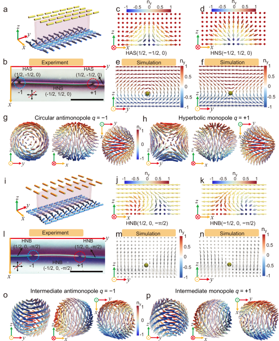
Fig. 1: Creation of topological monopole-antimonopole pairs in half skyrmions.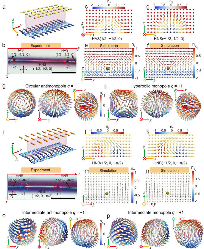
a Schematic of designed topological patterns. The bottom surface adopts alternating splay-bend distortions, and the top surface is along the y-axis. The half skyrmion strings are produced in the splay regions (pink). b Polarizing optical microscope (POM) image with an inserted red plate of two oppositely charged point defects in the half skyrmions. The red dashed line indicates the slow axis of a 530 nm retardation plate inserted between the polarizers. The red dotted circle denotes the monopole (q = +1), while the blue dotted circle indicates the antimonopole (q = −1). c Schematic vector field of a HAS (1/2, −1/2, 0) with far field F = 0; Red (blue) region shows that the y-component of the director is positive(negative), while the yellow region shows that the director is in-plane. d HNS (−1/2, 1/2, 0) with far field F = 0. e Simulated topological structures of a circular antihedgehog (q = −1) in the half skyrmion. f Simulated topological structures of a hyperbolic hedgehog (q = +1). g Vector field of the circular antihedgehog (q = −1). h Vector field of the hyperbolic hedgehog (q = +1). i Designed topological patterns. The bottom surface is alternating splay-bend distortions, and the top surface is along the x-axis. The half bimeron strings are produced in the bend regions (pink). j HNB (1/2, 0, −π/2) with far field F = −π/2. k HNB (−1/2, 0, −π/2) with far field F = −π/2. l Polarizing optical micrograph with an inserted red plate of two oppositely charged point defects in the half bimeron. m Simulated intermediate antihedgehog (q = −1) in the half bimeron. n Simulated intermediate hedgehog (q = +1) in the half bimeron. o Vector field of the intermediate antihedgehog (q = −1). p Vector field of the intermediate hedgehog (q = +1). All scale bars are 100 μm.
The topological configurations of the skyrmions (Supplementary Fig. 4) and monopoles (Supplementary Fig. 5–7) in our system are revealed through continuum simulations. A skyrmion (Nsk, m, F) in our model is characterized by three distinct parameters: the skyrmion number \({N}_{{sk}}\), vorticity \(m\) and far field (\(F\)), which is defined as the angular orientation of the uniform surface relative to the y-axis. We have identified the monopole located on the left in Fig. 1b as a circular antihedgehog with a topological charge \(q=-\!1\), as shown in Fig. 1e, g. Conversely, the monopole on the right in Fig. 1b is classified as a hyperbolic hedgehog with \(q=+\! 1\), as shown in Fig. 1f, h. The sign of the topological charge (\(q=\pm\! 1\)) is determined by applying the right-hand rule to the director field configuration. When the directors at three orthogonal surface points satisfy \({{{\boldsymbol{x}}}}\times {{{\boldsymbol{y}}}}={{{\boldsymbol{z}}}}\), the configuration represents a monopole (\(q=+\! 1\)); conversely, \({{{\boldsymbol{x}}}}\times {{{\boldsymbol{y}}}}=-{{{\boldsymbol{z}}}}\) indicates an antimonopole (\(q=-\!1\))38,52. The skyrmions associated with the monopole \(q=-\!1\) are designated as HAS (1/2, −1/2, 0) on the left-hand-side (Fig. 1c) and HNS (−1/2, 1/2, 0) (Fig. 1d) on the right-hand-side, respectively. Mathematical definitions of these topological textures are described in the Supplementary text. On the other hand, the monopole \(q=+ 1\) is linked to HNS (−1/2, 1/2, 0) on the left and HAS (1/2, −1/2, 0) on the right.
In our half skyrmion system, two half skyrmions are connected by monopoles, Fig. 1b–d. These half skyrmions exhibit identical polarities, denoted in blue, and share the same far field vector, represented in red. However, their vorticities, indicated in yellow, are vectors that point in opposite directions, leading to a discordance between them and the subsequent monopole formation. This opposition is a direct consequence of the boundary condition imposed by the top and bottom pattern designs. Details on skyrmion number, polarity, vorticity, and far field forms are elaborated in the Supplementary text. It is revealed that the formed monopoles in this experiment are circular (anti) hedgehog (q = ±1) and hyperbolic (anti) hedgehog (q = ±1) (Fig. 1g, h and Supplementary Fig. 6), also see Supplementary text. According to the simulation results, a circular antihedgehog with q = −1 and a hyperbolic hedgehog with q = +1 are shown in Fig. 1e, f, respectively, and Supplementary Fig. 7a–h.
Another type of skyrmion string, half bimerons, can also be created if the uniform alignment is along the x-axis (Fig. 1i–k). After the phase transition, monopole-antimonopole pairs are generated in the half bimeron (Fig. 1l and Supplementary Fig. 3c, d). The profile of the antimonopole (Fig. 1o) is different from both the circular and hyperbolic antimonopole shown in Fig. 1g and Supplementary Fig. 6c. This intermediate antihedgehog is obtained from the radial antihedgehog (q = −1) (Supplementary Fig. 5b) by rotating the director π/3 about a certain fixed axis at every point, see Fig. 1m and Supplementary Fig. 7i–l. Likewise, the intermediate monopole configuration (Fig. 1p) is obtained from the radial hedgehog (q = +1) (Supplementary Fig. 5a) by rotating the director 2π/3 about a certain fixed axis at every point, Fig. 1n and Supplementary Fig. 7m–p.
Topological transition of half skyrmions by monopole-antimonopole pair
When the far field is F = 0 (top uniform alignment along the y-axis), the skyrmion string is divided into three different half skyrmions by a monopole-antimonopole pair: HAS (1/2, 0) on both sides, and HNS (−1/2, 0) in the middle (Fig. 2a). Please note that, for convenience, the notation for skyrmions will be simplified to the form of skyrmion (Nsk, F) in the following text and figures. The monopole-antimonopole pair spontaneously move towards each other until they meet and annihilate (Fig. 2b, c and Supplementary Movie 1). During this process, the HNS (NSK = −1/2) string with a length of 180 μm completely converts to an HAS (NSK = 1/2) string within 41 s (Fig. 2d). This transition is driven by the pair annihilation of the circular antihedgehog (q = −1, Fig. 2b), and the hyperbolic hedgehog (q = +1, Fig. 2c), which act as the monopole and antimonopole of the emergent director field. However, when top uniform alignment along the −y-axis, F = π, the monopole-antimonopole pair repel each other and move out of the observation range (Supplementary Fig. 8a–d and Supplementary Movie 2). HNS (NSK = ±1/2) can also be stabilized by manipulating the monopoles using optical tweezers (Supplementary Fig. 8e and Supplementary Movie 3).
Fig. 2: Topological transformation of half skyrmions by monopole-antimonopole pairs.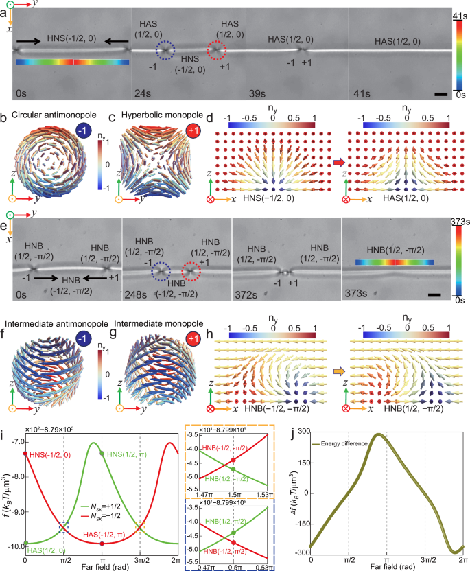
a Monopole-antimonopole pair formation, attraction and annihilation in a skyrmion string. The red dotted circle denotes the monopole (q = +1), while the blue dotted circle indicates the antimonopole (q = −1). b Vector field of the circular monopole with F = 0. c Hyperbolic antimonopole with F = 0. d Topological transition from HNS (−1/2,0) to HAS (1/2,0). e Monopole-antimonopole pair formation, attraction and annihilation in a bimeron string. f Intermediate antimonopole with F = −π/2. g Intermediate monopole with F = −π/2. h Topological transition from HNB (−1/2, −π/2) to HNB (1/2, −π/2). i Free energy comparison of different half skyrmions. The yellow (F = −π/2) and blue (F = π/2) frames are the enlarged parts of the energy comparison between HNBs in different far fields. j Under different far field conditions, the free energy difference ∆f between half skyrmions NSK = +1/2 and NSK = −1/2. Scale bars are 20 μm.
A similar phenomenon of mutual attraction and repulsion exists between the intermediate hedgehogs with opposite charges produced within the half bimeron (Fig. 2e and Supplementary Movie 4). When the uniform alignment on the top surface is along the −x-axis, F = −π/2, a half bimeron string is split into three segments by a monopole-antimonopole pair: HNB (1/2, −π/2) on both sides, and HNB (−1/2, −π/2) in the middle. The intermediate antihedgehog (q = −1) (Fig. 2f) and intermediate hedgehog (q = +1) (Fig. 2g) spontaneously annihilate, Fig. 2e. As a result, HNB (−1/2, −π/2) transforms into HNB (1/2, −π/2) (Fig. 2h). During this process, the 120 μm long HNB (NSK = −1/2) string completely converts to an HNB (NSK = 1/2) string within 373 s (Fig. 2e)
The simulations reveal that HNS (NSK = ±1/2) possess higher free energy (Fig. 2i). As a result, HNS (NSK = ±1/2) always transitions to HAS (NSK = ±1/2) through either annihilation (Fig. 2a) or repulsion (Supplementary Fig. 8a) of monopoles and antimonopoles. Additionally, there is an energy difference between HNB (NSK = −1/2) and HNB (NSK = +1/2), as shown in the inset of Fig. 2i. When F = 0 or π (in the splay region), a significant energy difference between HNS and HAS, \(\left|\Delta f\right| \sim 280{k}_{B}T/{{{{\rm{\mu }}}}{{{\rm{m}}}}}^{3}\), leads to a fast motion of the two defects (Fig. 2a, j). In contrast, when F = π/2 or −π/2 (in the bend region), the small free energy difference between the two HNB structures, \(\left|\Delta f\right| \sim 5{k}_{B}T/{{{{\rm{\mu }}}}{{{\rm{m}}}}}^{3}\), results in a slower motion of the defects (Fig. 2e, j).
Tunable topological transformation of half skyrmions
The half skyrmion strings can be driven to translational out-of-equilibrium by irradiating the uniform alignment with linearly polarized blue light (wavelength = 455 nm, beam intensity = 510 mW/cm²)21,53,54,55. Following the translated motion of half skyrmions, the mutual interaction of monopole-antimonopole can be tuned between attraction and repulsion, meanwhile inducing the topological transition of the half skyrmions. First, half bimerons are generated at locations of x = 0, 2L, …, if the top surface alignment is along the x-axis (Fig. 3a). At t = 0 s, the half bimeron is at x = 0 in the bend region. A pair of monopole and antimonopole is created in this half bimeron string, Fig. 3a, dividing a half bimeron string into three segments, with the middle part being an HNB(−1/2, −π/2), while the left and right parts are both HNB(1/2, −π/2).
Fig. 3: Tunable topological transformation of half skyrmions.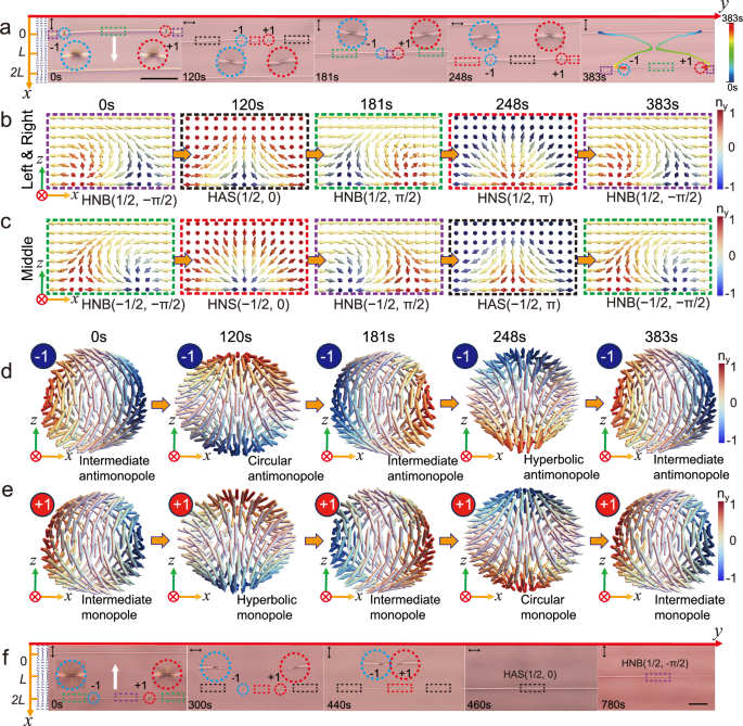
a Image sequence of the response of the monopole-antimonopole pair in the translation of half skyrmions. The white arrow indicates the translation direction. The colored trajectories of two defects are shown in the last frame at t = 383 s. Red and blue dotted circles mark the monopole (q = +1) and antimonopole (q = −1) configurations, respectively. b Topological profiles of the half skyrmion strings on the left and right sides change following the order: HNB(1/2, −π/2), HAS(1/2,0), HNB(1/2, π/2), HNS(1/2,π), and HNB(1/2, −π/2). c Topological profiles of the half skyrmion strings in the middle part follow the order: HNB(−1/2, −π/2), HNS(−1/2,0), HNB(−1/2, π/2), HAS(−1/2, π) and HNB(−1/2, −π/2). d Antimonopole configurations follow the order of an intermediate antimonopole(F = −π/2), a circular antimonopole, an intermediate antimonopole(F = π/2), a hyperbolic antimonopole and an intermediate antimonopole(F = −π/2). During this transformation process, topological charge (q = −1) remains unchanged. e Monopole configurations follow the order of an intermediate monopole(F = −π/2), a hyperbolic monopole, an intermediate monopole(F = π/2), a circular monopole and an intermediate monopole(F = −π/2). During this transformation process, topological charge (q = +1) remains unchanged. f The pair of oppositely charged defects is enabled to annihilate by controlling the irradiation. Scale bars are 100 μm.
Under light illumination, at t = 120 s, the half bimeron string moves to the splay region at x = L/2 (Fig. 3a and Supplementary Movie 5). The antimonopole moves towards the right and the monopole to the left, with the monopole-antimonopole pair exhibiting attraction-like interaction. The profiles of the antimonopole and monopole change from intermediate states to circular and hyperbolic, respectively, Fig. 3d, e. At the same time, the bimerons on the two sides are transitioned to HAS (1/2, 0) and the bimeron in between is transformed to HNS (−1/2, 0) (Fig. 3b, c). At t = 181 s, the string moves to the bend region at x = L. Half skyrmions continue to change into half bimerons (Fig. 3a–c). The monopole-antimonopole pair starts to move in opposite directions, exhibiting a repulsion-like interaction, Supplementary Movie 5. The bimerons on the two sides are transformed to HNB(1/2,π/2) while the middle part to HNB(−1/2, π/2), Fig. 3b, c. The profiles of the antimonopole and monopole continue to change to intermediate, respectively, Fig. 3d, e. At t = 248 s, the string moves to the splay region at x = 3L/2, the bimerons on the two sides are transitioned to HNS(1/2, π) while the middle part to HAS (−1/2, π), Fig. 3b, c. The profiles of the antimonopole and monopole change to hyperbolic and circular, respectively and the pair shows strong repulsion-like interaction, Fig. 3d, e. At t = 383 s, the skyrmion string completes the translation with a period of 2L = 100 μm, the monopole pair starts to move to each other, exhibiting attraction-like interaction again.
On the left and right sides, the topological structures of the half skyrmion strings are transformed in the following order: HNB(1/2, −π/2), HAS(1/2,0), HNB(1/2, π/2), HNS(1/2, π), and HNB(1/2, −π/2). The transformations in the middle part occur in the following order: HNB(−1/2, −π/2), HNS(−1/2, 0), HNB(−1/2, π/2), HAS(−1/2, π) and HNB(−1/2, −π/2). The configurations of the antimonopole and the monopole keep changing, but the charge remains unchanged. Single point defect in the half bimeron string can also be manipulated by light irradiation to achieve the topological transitions of half skyrmions (Supplementary Fig. 9 and Supplementary Movie 6).
During this process, since HAS (NSK = ±1/2) possesses lower energy than HNS (NSK = ±1/2), Fig. 2i, the monopoles move to HNS, leading to the growth of HAS. Due to the motion of the monopoles, the lengths of the skyrmion strings are tuned by light irradiation; meanwhile, the skyrmion number remains unchanged due to topological protection when the above four topological textures are mutually transformed. Likewise, the profiles of the monopoles are constantly changing, meanwhile the charges (q = ±1) are topological protected and remain constant. It is worth mentioning that the addition of an external optical field is crucial in enabling the interconversion among the four types of monopole structures and effectively prevents the annihilation between monopoles of opposite charges. For instance, in Fig. 3f, at t = 440 s, the monopole-antimonopole pair is very close. If illumination stops, they would inevitably meet and annihilate (Supplementary Movie 7). Afterwards, the whole skyrmion string is transitioned to an HAS(1/2,0) with NSK = +1/2. Thus, the topological transition between different skyrmion strings can be tuned by controlling the mutual interaction of the monopole-antimonopole pair through programming the light irradiation.
A monopole-antimonopole pair in half skyrmion string loops
When the director field on the bottom surface is given by \(\hat{{{{\bf{n}}}}}=({n}_{x},{n}_{y},{n}_{z})=(\cos \alpha,\sin \alpha,0)\), with \(\alpha=\frac{\pi \sqrt{{x}^{2}+{y}^{2}}}{L}\), and the top surface is aligned along the −x-axis, a half skyrmion loop containing 4 different half skyrmion types is formed21 (Fig. 4a, b and Supplementary Fig. 10a). After phase transition, a pair of opposite charged monopoles were created within the loop. The loop is determined to be composed of six alternating segments of half skyrmions and half bimerons (Supplementary Fig. 10b, c). Both the monopole and antimonopole adopt intermediate profiles, and they are positioned in the opposite bend regions (Fig. 4b–d). By calculating the free energy of the entire system, the system has only one stable state, achieved when the azimuthal angle of the monopole (q = +1) is φ+1 = 0° and that of the antimonopole (q = −1) is φ−1 = 180°, as shown in Fig. 4d, e (t = 0 s).
Fig. 4: A monopole-antimonopole pair in half skyrmion loops.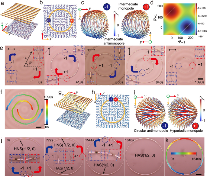
a Schematic of director fields of top and bottom surfaces. b Through phase transition, a monopole-antimonopole pair is generated in the loop and stably located in the bend regions. c Two intermediate hegehog structures with opposite charges. d The free energy calculation reveals that the monopole and antimonopole are stabilized at \({\varphi }_{+1}=0^\circ\) and \({\varphi }_{-1}=180^\circ\). e Image sequence of dynamics of monopole-antimonopole during loop shrinkage. Double arrow indicates the top uniform alignment. Red and blue dotted circles mark the monopole (q = +1) and antimonopole (q = −1) configurations, respectively. f The colored trajectories of two defects. g Schematic of director fields of top and bottom surfaces. h Director field of the bottom surface. i Circular hedgehog with a negative charge and hyperbolic hedgehog with a positive charge. j Image sequence showing the autonomous motion of a monopole-antimonopole pair in a pure half skyrmion loop. k Colored trajectories of the two defects. (Scale bar, 100 μm).
Next, the string loop is driven out-of-equilibrium to shrink by light irradiation (Fig. 4e, f and Supplementary Movie 8). During the shrinking process, the monopole-antimonopole pair rotates clockwise (CW) along the string. For example, at t = 0 s, the monopole and antimonopole are located at φ+1 = 0 and φ−1 = π, respectively, Fig. 4e. Upon irradiation, as the top surface alignment changes to the y-axis at t = 410 s, the monopole-antimonopole pair rotates 90° CW to φ+1 = −π/2 and φ−1 = π/2, Fig. 4e. Continuous rotation of the uniform alignment to the x-axis results in the monopole and antimonopole at φ+1 = π and φ−1 = 0 at t = 650 s (Fig. 4e). After one full period of string loop shrinkage, the motion trajectory of the monopole pair manifests two spiral shapes, as shown in Fig. 4f (t = 1090 s).
Note that the topological charges and profiles of the monopole-antimonopole pair remain unchanged throughout the loop shrinking process, as they are always drawn to the bend regions with the lowest energy within the system (Fig. 4d and Supplementary Fig. 10f). Since the pair moves in the same direction and at the same speed, they will never meet each other unless the loop is annihilated. During the expansion of the loop, the pair will rotate counterclockwise (CCW) along the loop in response to the light irradiation with unchanged topological charges (Supplementary Fig. 10d–f and Supplementary Movie 8).
When the director field on the bottom surface adopts \(\hat{{{{\bf{n}}}}}=({n}_{x},{n}_{y},{n}_{z})=(\cos \alpha,\sin \alpha,0)\), where \(\alpha=\frac{\pi \sqrt{{x}^{2}+{y}^{2}}}{L}+{{{\rm{a}}}}{{{\rm{rctan}}}}\frac{y}{x}\) (Fig. 4h) and the top surface is designed as \(\hat{{{{\bf{n}}}}}=({n}_{x},{n}_{y},{n}_{z})=(\cos \alpha,\sin \alpha,0)\), with \(\alpha \left(x,y\right)=m{\tan }^{-1}\frac{y}{x}+{\alpha }_{0}\), where m = +1 is an integer topological charge, and \({\alpha }_{0}=\frac{\pi }{2}\) sets the distortion with a pure bend (circular pattern) (Fig. 4g, h), a pure half skyrmion loop of HNS(−1/2,0) is generated. In Fig. 4j and Supplementary Movie 9, at t = 0 s, after phase transition, a pair of monopole and antimonopole is created in this pure half skyrmion loop (Fig. 4i), resulting in the loop being composed of two different types of half skyrmions, HNS(−1/2,0) and HAS(1/2,0). Afterwards, the circular antimonopole(q = −1) autonomously rotates CW along the loop, while the hyperbolic monopole(q = +1) rotates CCW concurrently until they meet and annihilate. Finally, at t = 1640 s, the loop becomes a pure HAS(1/2,0). The physical underpinning is consistent with the situation shown in Fig. 2. Besides, the annihilation of intermediate monopole-antimonopole pairs in the pure half bimeron loop is also demonstrated (Supplementary Fig. 10g–k and Supplementary Movie 9).
Colloidal transport by monopole-enabled topological transition of skyrmions
A spiral shaped pure half skyrimon HAS(1/2,0) is created, Fig. 5d, when the director field on the bottom surface follows \(\hat{{{{\bf{n}}}}}=({n}_{x},{n}_{y},{n}_{z})=(\cos \alpha,\sin \alpha,0)\), where \(\alpha=\frac{\pi \sqrt{{x}^{2}+{y}^{2}}}{L}\) (Fig. 5a), and the top surface is designed as \(\hat{{{{\bf{n}}}}}=({n}_{x},{n}_{y},{n}_{z})=(\cos \alpha,\sin \alpha,0)\), with \(\alpha \left(x,y\right)={\tan }^{-1}\frac{y}{x}+\frac{\pi }{2}\) (Fig. 5b, c).
Fig. 5: Colloidal transport by monopole-enabled topological transition of skyrmions.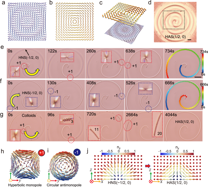
a Director field of the bottom surface. b Director of the field of the top surface. c 3D schematic of the assembled cell. d Spiral-shaped half skyrmion HAS(1/2,0). e The hyperbolic monopole (q = +1) in the spiral-shaped string spontaneously moves from the center to the boundary along the string, the colored trajectory of the monopole is shown in the last image at t = 734 s and (f) The circular antimonopole (q = −1) in the spiral-shaped string spontaneously moves from the boundary to the center along the string, the trajectory is shown in the last image at t = 666 s. g The hyperbolic monopole (q = +1) in the string collects colloidal particles during its spontaneous movement within the string and transports them from the center to the boundary. A pure spiral-shaped skyrmion string is shown after the colloids are cleared from the skyrmion at t = 4044 s. h Hyperbolic hedgehog with a positive charge. i Circular antihedgehog with a negative charge. j Half skyrmion structures can continuously change from HNS (NSK = −1/2) to HAS (NSK = +1/2) by motion of monopoles. Red and blue dotted circles mark the monopole (q = +1) and antimonopole (q = −1) configurations, respectively. (Scale bar, 100 μm).
A monopole-antimonopole pair is generated after the phase transition. At t = 0 s, the circular antimonopole (q = −1) is moved by the optical tweezer to the boundary of the pattern and eliminated, while the hyperbolic monopole (q = +1) is brought closer to the center position (Fig. 5e, h, and Supplementary Movie 10). As such, the skyrmion string is of HNS(−1/2,0) (Fig. 5j). Due to the instability of HNS(−1/2,0) and the lower energy state of HAS(1/2,0), the hyperbolic monopole spontaneously moves from the center following the spiral trajectory at an average speed of 2 μm/s (Supplementary Fig. 11f) and HNS(−1/2,0) is transformed to HAS(1/2,0) (Fig. 5j). On the contrary, a circular antimonopole (q = −1) can be created close to the boundary and moves with an average speed of 2.32 μm/s (Supplementary Fig. 11g) towards the center along the half skyrmion (Fig. 5f, i and Supplementary Movie 10).
We have developed the transport function of the monopoles in the spiral half skyrmion string. Colloidal particles in different numbers are placed within the spiral string at different positions. The motion of the monopoles enables the transport of a colloidal chain (20 colloids) from the center to the boundary (Fig. 5g and Supplementary Movie 11) or from the boundary to the center (Supplementary Fig. 11e and Supplementary Movie 11). Note that the speed of point defects decreases as the number of colloidal particles increases. For example, a colloidal chain propelled by the hyperbolic monopole (q = +1) exhibits an average speed of 0.35 μm/s (Supplementary Fig. 11h). This corresponds to an Ericksen number Er ≪ 1, which is orders of magnitude smaller than the flow speed (tens to 103 μm/s with Er = 2 ~ 100) required for director reorientation56,57. Thus, hydrodynamic effects are negligible in this regime.