
Figure 1a-i shows a representative cross-section through our sample that consists of a CrSBr bilayer with adjacent flakes of three and seven layers, respectively (see Fig. 1b for an optical image), and the expected spin configuration after zero-field cooling of the sample24. CrSBr is an easy-axis AF, where the easy axis (the “b-axis”) lies in the vdW plane and where spins order ferromagnetically within a plane and antiferromagnetically between planes19. As a result, CrSBr samples with an even (odd) number of layers carry zero (nonzero) magnetization, respectively.
Fig. 1: Controllable lateral exchange bias.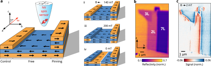
a-i Schematics of the exfoliated CrSBr sample after zero-field cooling. A diamond tip with an embedded NV center, and the angle between the NV center and the sample plane are represented. ii-iv Schematics of the sample after the successive application of 140 mT, 200 mT and 0 mT fields along the crystalline b-axis. b Optical image of the flake obtained by measuring the reflectance of a 640 nm laser. Stacks of 2, 3 and 7 layers are labeled. c Dual-Iso-B (see SI section III) magnetic image of the flake for an external in-plane field of 2 mT.
To assess the magnetic state of our sample and image its spin textures, we employ direct magnetic imaging using scanning nitrogen-vacancy (NV) magnetometry. In short, NV magnetometry exploits the electronic spin of the NV centre as a sensitive magnetometer that can be initialized and read out optically and driven by microwave magnetic fields25. To achieve nanoscale imaging, the NV spin is embedded in a diamond tip26 to be scanned within ≈50 nm from the sample. In this work, we exploit both qualitative (Dual-Iso-B) and quantitative (ODMR) imaging modes as described in the Supplementary Information (SI) section III, where we use the former for rapid assessment of spin configurations and the latter for detailed quantitative analysis of the resulting spin textures. Figure 1c shows a qualitative NV magnetometry image of our sample that shows stray field patterns consistent with the spin arrangement illustrated in Fig. 1a-i24. All data we present have been obtained at a temperature of T ≈ 4 K in a cryogenic scanning NV magnetometry apparatus with vector magnetic field control described elsewhere24,27. When performing NV magnetometry in external magnetic fields, we align these fields with the NV spin quantization axis eNV to ensure optimal performance28, and mount our samples such that eNV lies in the sample’s b-c-plane, tilted ≈54° from the c-axis (Fig. 1a-i). Due to the weak response of CrSBr to magnetic fields along c29, we state the magnitude of the b-axis component, Bb, whenever a field is applied.
A possible approach to exploit the LEB for Néel vector control is shown in the sequence of illustrations in Fig. 1a,i–iv. Following a sequence of increasing magnetic field Bb, where first, the bilayer undergoes a spin-flip transition at Bb ≈ 140 mT29,30,31,32, and subsequently, the trilayer switches its magnetisation at Bb ≈ 200 mT5. Importantly, the 7-layer flake (that we will refer to as “pinning layer” in the following) remains unaffected by this process as the spin-flip field values in few layers CrSBr depend on the exact number of layers, and tend to increase with the flake thickness33 (see SI section V). The flip of the trilayer (that we will refer to as the “control layer” in the following) exposes the bilayer to LEB of opposite signs at the boundaries to the control and pinning layer, respectively. Upon reduction of Bb below BSF, AF phases of opposing Néel vector orientation will thus emerge from the two boundaries, resulting in the expected final spin arrangement shown in Fig. 1a–iv.
We begin by experimentally assessing the effectiveness of the LEB. For this, we focus on the regime Bb ≈ BSF,2, where the bilayer is in a state of phase-coexistence between FM and AF phases24,34, corresponding to the steps 2 and 4 of the external field sequence presented in Fig. 2a. Figure 2b shows a schematic of the magnetic state of the flake that we infer from the magnetic image obtained at Bb = 144 mT (Fig. 2c). Importantly, we find that the LEB has a striking effect on the trajectory of AF-FM phase walls within the bilayer when they impinge on the adjacent pinning layer. Specifically, towards the intersection with the bilayer-pinning-layer interface, the phase walls show striking and reproducible distortions away from the normal incidence observed and expected35 when the phase wall impinges on the flake boundary. These distortions are well explained by the energetics of the LEB at the bilayer-pinning-layer interface (see Fig. 2d): Where the bilayer has FM spin alignment, the interface incurs an energy penalty corresponding to a head-to-head domain wall in a single CrSBr monolayer. Conversely, if the bilayer is in the AF phase, the interface energy depends on its Néel-vector orientation. For the arrangement represented in Fig. 2d, the interface energy corresponds to a head-to-head domain wall in two CrSBr monolayers, while for the opposite Néel vector orientation, the interface energy is zero. To minimize energy, the length of the low-energy bilayer-pinning-layer interface will thus expand at the expense of the high-energy interface. This expansion distorts and extends the phase wall, where both represent additional energy penalties. The process stops when the energy reaches a local minimum, leading to the distorted phase wall trajectory shown in Fig. 2e. This behavior can be seen as a magnetic analogy of wetting in hydrostatics, where the phase wall forms a “contact angle” with the pinning layer (see SI section VII).
Fig. 2: Lateral exchange bias induced phase wall steering.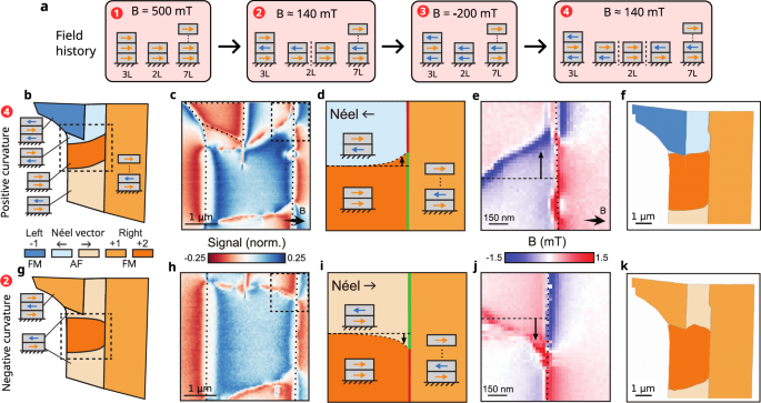
a External magnetic field sequence applied along the easy axis of the flake, with expected magnetization for each stack. b–f Correspond to step 4 and g–k to step 2. See SI sections VI and VII for more details. b Schematics of the magnetic state in the flake for an external field of 144 mT. c Dual-Iso-B magnetic image of the flake in the region highlighted in the schematics. See SI section IV for a full scale imaging of the bilayer. Dotted lines indicate the boundaries between regions of different thicknesses. d Illustration of the phase wall distortion at the pinning layer interface. The boundary part painted in red has a higher interfacial energy than the green part. Deviation from normal incidence is noted by a black arrow. e ODMR magnetic image of the interface region. Dotted line and black arrow indicate deviation from normal incidence. f Micromagnetic simulation of the flake following color code in a (Simulation details in SI section V) g–k Same as b–f with the control layer’s magnetization flipped.
We confirmed this intuitive picture through numerical micromagnetic simulations described in detail in the SI section V. Figure 2e shows a representative simulation result for the steady state spin configuration in a model CrSBr system that mimics the geometry of our sample. Importantly, the simulation yields a phase wall trajectory and FM/AF coexistence that are in good qualitative agreement with our data.
Next, we performed a control experiment in which we investigated the effect of LEB on the phase wall trajectory for the opposite Néel-vector orientation compared to the previous case (Fig. 2g–k). We first applied a positive field Bb = 340 mT to invert the control layer magnetization. When reducing Bb towards BSF,2, an AF pocket preferentially nucleates at the interface to the control layer24, and, owing to LEB, will have its Néel vector flipped compared to the case discussed before. This assertion is confirmed by the strikingly different phase wall behavior that we observe in this case at Bb ≈ BSF,2 (Fig. 2g). The phase wall is now deflected in the opposite deflection compared to before as a result of the modified energetics at the bilayer-pinning-layer interface. This picture is again verified by the micromagnetic model as shown in Fig. 2j.
We now apply our knowledge of the LEB for the deterministic writing of a domain wall in our AF-ordered CrSBr bilayer. Starting from the experimental state shown in Fig. 2b, we reduce the magnetic field to below BSF,2, where all of the bilayer is AF ordered. Figure 3b shows a corresponding sequence of magnetic images that display the evolution of the bilayer spin texture with decreasing field. Strikingly, at Bb = 131 mT, we find that the bilayer is divided by a well-pronounced line of nonzero stray field. Based on our assessment of the bilayer’s spin structure we associate this line with the presence of an AF domain wall (Fig. 3c). A control experiment further confirms this interpretation: If the sequence is repeated from the starting configuration presented in Fig. 3d no domain-wall would be expected, and indeed, a perfectly homogeneous AF region results in the bilayer (Fig. 3e).
Fig. 3: LEB enabled anti-ferromagnetic domain wall control.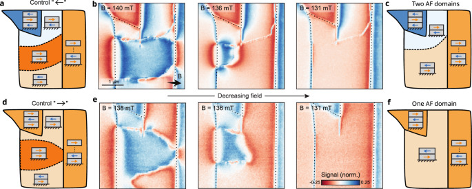
a Schematics of the flake magnetic state at B ≈ 140 mT when the control layer is flipped to the left. b Dual-Iso-B magnetic images of the flake as a function of a decreasing external field. Dotted lines indicate the boundaries between regions of different thickness. c Schematics of the flake magnetic state at B ≈ 130 mT. d–f Same as a–c with the control layer flipped to the right.
While a determination of the exact domain wall structure is out of the scope of this work, our simulations indicate that it is of Néel nature. The observed, nonzero domain wall stray field appears to originate from spin-canting induced by the in-plane (b-axis) component of the applied field, as its magnitude depends on the domain wall angle (excluding an out of plane canting) and increases with the applied field. When repeating the experiment, we observed the domain wall at different, random locations on the sample (see SI section VIII), which indicates that domain-wall motion is not strongly affected by pinning. We also successfully applied this sequence and produced a domain wall on an additional bilayer sample (See SI section IX).
Finally, our experiment also revealed an instance of AF domain decoration. Figure 4a shows the outcome of a new instance of the domain-wall writing sequence, where the resulting domain wall crosses a ≈200 nm wide CrSBr trilayer that extends from the control layer into the bilayer (see SI section I). A quantitative magnetometry scan (Fig. 4b, c) reveals that, by virtue of the AF interlayer exchange interaction, the domain structure of the bilayer is imprinted onto that trilayer that is now split into a two-domain state (see illustration in Fig. 4d). The resulting twenty fold increase of the domain wall stray field on the narrow trilayer compared to the bulk bilayer (Fig. 4e), suggests that such thin stripes act as efficient decorations for underlying AF domains and may thereby enable detection of such domains near zero magnetic field, where the domain wall stray-field is otherwise undetectable.
Fig. 4: Decoration of antiferromagnetic order.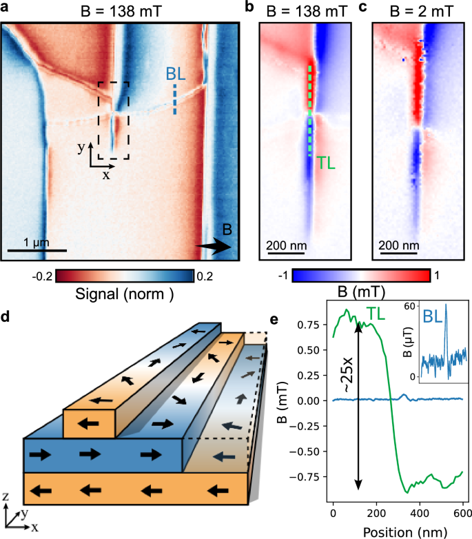
a Dual-iso-B magnetic image of AF domain wall intersecting a thin FM layer and imprinting onto it. b, c ODMR magnetic images of the AF-FM domain wall interface at the initialisation field of Bb = 138 mT and with the field reduced to near zero Bb = 2 mT, respectively. d Schematic of the in-plane spin rotations of each layer at the domain wall interface. e Linecuts of the magnetic field from the bilayer (blue) and trilayer (green) domain walls, as shown in a and b, with an approximate 25× difference in magnitude.
In conclusion, we have established the LEB as a novel tool for Néel-vector control in vdW AFs. Importantly, our concept readily extents to other vdW magnets and should, in particular, apply to any a-type vdW AF, including the prominent examples CrI32, CrCl336or CrPS437, where our “wetting” angle methodology could also be applied to assess interfacial exchange energies.
Our results build on the single crystalline nature of vdW magnets, which offers atomically sharp lateral interfaces—a key factor that sets them apart from their thin-film counterparts and that results in a remarkable enhancement in the reach of EB: While in thin-film geometries11,12, each interfacial spin from the pinning layer controls tens of spins in typically nanometers-thin target layers, in our LEB, each interfacial spin controls a row of spins extending microns into the target layer—an extension of the effective range of EB by several orders of magnitude.
Our work opens up exciting future avenues, not only towards the fundamental understanding of domain walls38 and domain formation in atomically thin AFs, but also in the recently explored interplay between magnetism and optical and magnetic excitations of CrSBr5. Indeed, excitons and magnons appear strongly coupled in this system39, which, together with magnon guiding on spin textures40, might enable engineered magnon-exciton dynamics, controlled by LEB-written AF domain walls.