
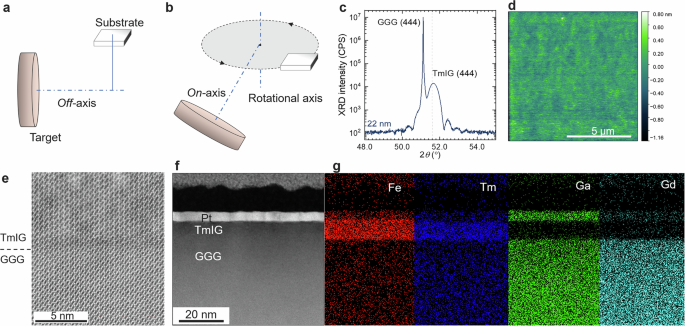
TmIG films were grown on a GGG substrate using the on-axis RF magnetron sputtering technique at room temperature (Fig. 1b). Argon gas was introduced at a flow rate of 23 sccm after the optimization (see Supplemental Material S1). Post-annealing of the TmIG film was performed in an O2 atmosphere at 800° C for 180 min to gain their crystallinity and magnetic properties. Pt film was deposited by dc-sputtering. Hall cross devices of TmIG/Pt heterostructures were fabricated by lithography and Ar+ ion milling.
The crystal structure was examined by XRD patterns of 22 nm-thick TmIG film as shown in Fig. 1c. A Clear peak at 51.6° stemming from a strained TmIG (444) plane was observed in addition to the sharp peak from the GGG (444) plane. The peak of the TmIG (444) plane was the same as that observed in previous reports6,23,34. From these patterns, the out-of-plane lattice constant a(111) was 1.2275 nm.
To examine the crystal quality of a representative sample, a series of characterization was performed using an atomic force microscope (AFM) and a scanning transmission electron microscope (STEM). A flat surface with root-mean-square (RMS) roughness of 0.14 nm was observed (Fig. 1d). This excellent crystallinity of the TmIG film was also observed by a cross-sectional high-angle annular dark-field (HAADF) STEM image with atomic resolution and zone axis [110] (Fig. 1e). The STEM image disclosed that our TmIG film has the same crystal structure and orientation as the GGG (111) substrate. A sharp interface without atomic interdiffusion was confirmed by elemental mapping (Fig. 1e,f).
The magnetic properties were examined using the Magneto-optical Kerr effect (MOKE) and the superconducting quantum interference device (SQUID). MOKE signal under an out-of-plane field shows clear hysteresis expected from a PMA ferromagnet. From SQUID magnetometry, the signal measured in an out-of-plane magnetic field shows clear hysteresis, while the in-plane field scan shows the hard axis properties, indicating that the easy axis was normal to the film surface (Fig. 2a, b). The MS is measured to be 100 kA/m, which is also in line with previous reports34,36. Figure 2c shows the magnetic field-dependent spin wave difference measured by Brillouin light scattering (BLS) using a 24 nm-thick TmIG film. Based on the clear Stokes peaks, the magnetic anisotropy was evaluated. The magnetic field dependent spin wave frequency curve is expressed by37:
$$f=\frac{\gamma }{2\pi }\sqrt{H\left(H+{M}_{{\rm{eff}}}\right)},$$
(1)
where γ is gyromagnetic ratio, \({M}_{{\rm{eff}}}={\mu }_{0}{M}_{{\rm{S}}}-2{K}_{{\rm{u}}}/{M}_{{\rm{S}}}\) is the effective magnetization. From the fitting, Meff and Ku was evaluated as 64.3 mT and 9.5 kJ/m3, respectively, which are in line with previous studies34,38. The signal of the anti-Stokes peaks was three orders smaller in amplitude than the Stokes peaks and unclear in our BLS measurement. Although non-zero Dzyaloshinskii-Moriya interaction (DMI) has been detected from TmIG16, it was not quantified in our experiment because of the unclear signal of anti-Stokes peaks. DMI energy density is defined as the frequency difference between Stokes and anti-Stokes peaks in the BLS experiment. Hence, it is important that both Stokes and anti-Stokes peaks are well defined to extract DMI energy37. The characterization of DMI in the on-axis sputtered TmIG films will be investigated in future experiments.
Fig. 2: Magnetic characterization of TmIG film and TmIG/Pt heterostructures.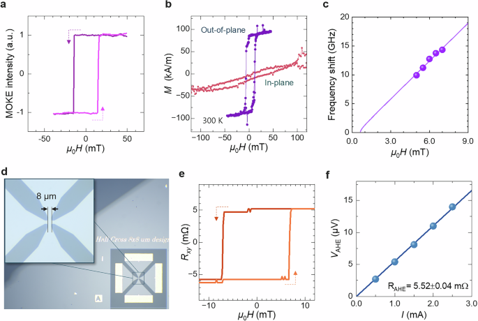
a Results of magneto-optic Kerr effect (MOKE) measured under an out-of-plane magnetic field. The light and dark violet colors represent the positive and negative sweeps, respectively. b Results of magnetometry measured at 300 K for in-plane and out-of-plane. c The magnetic field dependence of spin wave frequency measured by Brillouin light scattering. The solid symbols and the line represent the experimental result and the fitting line by Eq. (1), respectively. d Optical image of TmIG/Pt Hall cross devices patterned with photolithography. The inset shows a magnified view of the Hall cross structure. e Anomalous Hall effect measured at room temperature for a TmIG/Pt heterostructure with a bias current of 1 mA after the subtraction of the ordinary Hall effect component. f Bias dependence of the anomalous Hall signals where \({V}_{{\rm{AHE}}}=({V}_{{xy}\left(+{M\rm{sat}}\right)}-{V}_{{{xy}}\left(-{M\rm{sat}}\right)})/2\). \({{{V}}}_{{{xy}}\left(+{M\rm{sat}}\right)}\) is the transverse voltage at saturation in the positive field and \({{{V}}}_{{{xy}}\left(-{M\rm{sat}}\right)}\) in the negative field. The solid symbols and the line represent the experimental results and linear fitting, respectively.
Hall cross devices (Fig. 2d) were fabricated on TmIG/Pt heterostructures, with thicknesses of 6 nm and 3 nm, respectively. First, the anomalous Hall effect (AHE) was examined by applying a charge current (in the x-direction) and measuring the transverse voltage (in the y-direction) while sweeping the z-directional external magnetic field. The AHE in Fig. 2e shows a clear rectangular hysteresis with a coercivity of 7 mT, showing perpendicular magnetic anisotropy of TmIG at room temperature. The AHE observed in our sample was identified to originate from spin Hall magnetoresistance (more details in Supplemental Material S2). The bias current dependence of AHE was measured to estimate RAHE to be 5.52 mΩ from the linear fitting (Fig. 2f).
Current-induced spin-orbit torque magnetization switching
Considering the application potential of the TmIG/Pt system for various spin-orbitronic devices, current-induced magnetization switching is very important, which was measured with a pulse current, as shown in Fig. 3a. We observed the reproducible deterministic SOT switching of the TmIG/Pt device at room temperature (Fig. 3b). In the presence of an external field in x-direction and a charge current, the magnetization is switched from the −z direction to the +z direction. The switching direction is opposite when we reverse the external field direction, which agrees with SOT-driven magnetization switching. The critical current density (Jsw) was in the range of 0.7 to 1.5 × 10¹¹ A/m2. The asymmetry of the switching curve is sometimes observed in the SOT switching experiment. A possible reason is the x-component of the applied magnetic field, which has been discussed in ref. 39. The in-plane field as low as 5 mT was enough for breaking the rotational symmetry and observation of SOT switching. Robust and deterministic switching by pulse current was observed by applying consecutive pulse currents. The magnitude of the pulse current was in the range of +5.0 mA to +5.5 mA for the positive polarity and from -5.5 mA to -5.0 mA for the negative polarity, as shown in Fig. 3c. The polarity of the 50 μs-width-pulse current switches the anomalous Hall voltage, which was measured by applying a 0.5 mA for sensing (Fig. 3d).
Fig. 3: Current-induced spin-orbit torque magnetization switching in TmIG/Pt Hall devices.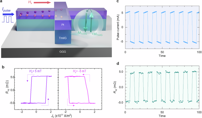
a Schematic diagram of switching measurements performed on TmIG/Pt heterostructures. A current pulse is applied to Pt along the x-axis, which generates a spin current through SHE along the z-axis, with spins oriented in the y-direction. An external magnetic field is also applied in the current direction to assist in magnetization switching. b Current-induced magnetization switching loops for TmIG/Pt heterostructures under external fields of + 5 and −5 mT. c, d Spin-orbit torque magnetization switching. The magnitude of consecutive applications of the 50 μs-width-pulse currents was from −5.5 to −5.0 mA in the negative polarity and from 5.0 mA to 5.5 mA in the positive polarity. The switching experiments were performed under an in-plane field of -5 mT (c). The Hall voltage was measured and plotted by applying 0.5 mA, 100 ms after each pulse current application (d).
Estimation of spin-orbit torque fields by second harmonic Hall measurements
The second harmonic measurement of the Hall voltage is a powerful tool for evaluating the SOT acting on perpendicularly magnetized magnetic films. We carried out a series of second-harmonic Hall measurements to extract the effective spin Hall angle in our device. The in-plane field scan was carried out to evaluate the damping-like torque generated by the spin Hall effect in Pt and acting on TmIG. The second harmonic signal \({V}_{2\omega }\) is expressed as the following23:
$$\begin{array}{lll}{V}_{2\omega }^{\phi =90^\circ }&=&\left({V}_{H}^{\mathrm{AHE},\mathrm{SMR}}-2{V}_{H}^{\mathrm{SMR}}\cos \theta \sin 2\phi \right)\frac{d\cos \theta }{dH}\frac{{H}_{FL}}{\sin \left({\theta }_{H}-\theta \right)}\\&& +\,2{V}_{H}^{\mathrm{SMR}}{\sin }^{2}\theta \cos 2\phi \frac{{H}_{DL}}{H\sin {\theta }_{H}}\end{array}\,$$
(2)
where H, \({\theta }_{H}\) and ϕ are the magnitude, and the zenith and azimuth angles of the external magnetic field, respectively. θ is the zenith angle of the magnetic moment of TmIG (see Fig. 4a). \({V}_{H}^{{\rm{SMR}}}\) and \({V}_{H}^{{\rm{AHE}},{\rm{SMR}}}\) are the measured voltages stemming from spin Hall magnetoresistance (SMR) and the SMR-induced anomalous Hall effect, respectively. HFL and HDL are the field-like and the damping-like torque induced by spin-orbital torque. Since \({V}_{H}^{{\rm{SMR}}}\gg {V}_{H}^{{\rm{AHE}},{\rm{SMR}}}\,\)(see Supplemental Material S2), the second term is dominant to the total signal, Eq. (2) will be further reduced to
$${V}_{2\omega }^{\phi =90^\circ }=2{V}_{H}^{{\rm{SMR}}}{\sin }^{2}\theta \frac{{H}_{{DL}}}{H\sin {\theta }_{H}}$$
(3)
Fig. 4: Second harmonic Hall measurements in TmIG/Pt Hall devices.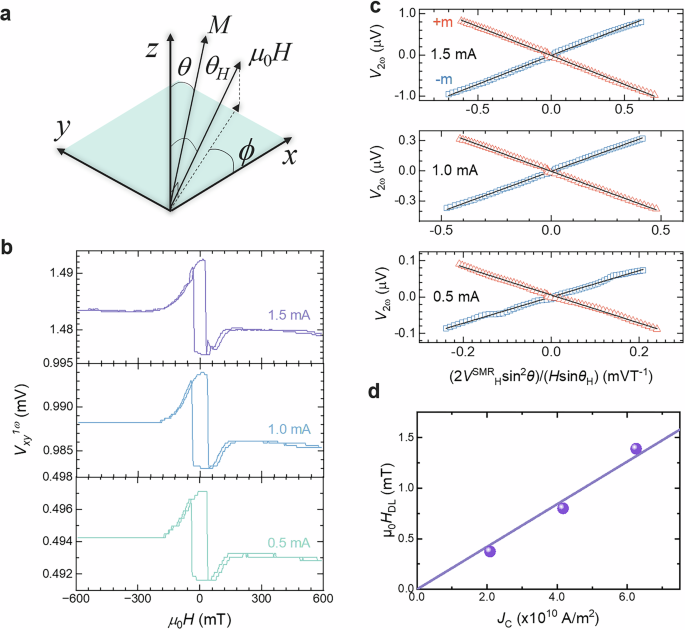
a Schematic diagram indicating the angular parameters used for the analysis of the second harmonic signal. b In-plane field dependence of first harmonic Hall voltage with different current biases. c Linear fitting of the second harmonic Hall signals based on Eq. (3). d Current density dependence of the damping-like torque measured by the second harmonic Hall voltages.
The first harmonic in-plane field scan for 0.5, 1.0, and 1.5 mA is shown in Fig. 4b. To estimate the damping-like SOT, V2ω versus a function of \((2{V}_{H}^{{SMR}}{\sin }^{2}\theta )/(H\sin {\theta }_{H})\) was plotted as shown in Fig. 4c. Following Eq. (3), the linear fitting was performed, and the slope yielded an effective damping-like field, HDL. Then, the current density JC dependence of HDL was plotted as shown in Fig. 4d. The effective spin Hall angle \({\theta }_{{\rm{SHE}}}^{{\rm{DL}}}\) was evaluated based on the equation23,29,40:
$${\theta }_{{\rm{SHE}}}^{{\rm{DL}}}=\left(\frac{2e}{\hslash }\right)\left(\frac{{H}_{{DL}}}{{J}_{C}}\right){M}_{{\rm{S}}}{t}_{{FM}},$$
(4)
where e is an elementary charge, ħ is the reduced Planck constant, MS is the saturation magnetization, and \({t}_{{FM}}\) is the thickness of TmIG. The \({\theta }_{{\rm{SHE}}}^{{\rm{DL}}}\) of the TmIG/Pt sample was 0.030.
To examine the effects of growth conditions and energetic anion irradiation on TmIG film, the \({\theta }_{{\rm{SHE}}}^{{\rm{DL}}}\) and \({J}_{{\rm{sw}}}\) in the TmIG/Pt system fabricated by different methods in the literature are compared in Table 1. Although some variation can be seen, no remarkable differences are found compared to those reported in the previous research using laser ablation and off-axis sputtering techniques. Some variations in \({\theta }_{{\rm{SH}}}^{{\rm{DL}}}\) and \({J}_{{\rm{sw}}}\) compared to the literature can be attributed to the thickness of TmIG, the quality of Pt film, and the interface between TmIG and Pt, as no significant difference in the magnetic properties of on-axis sputtered TmIG films could be observed.
Table 1 List of spin-orbit torque efficiency measured in Pt/TmIG systems
The critical current density depends on the efficiency of the SOT and the volume of the magnet. In the TmIG/Pt system, all the charge current flows in the Pt. Part of the charge current is converted into a spin current at a conversion rate, modulated by the effective spin Hall angle. The spins accumulate at the interface of TmIG/Pt and exert torque on the magnetic moment of TmIG23. The magnetization is detected via the anomalous Hall effect due to the spin Hall magnetoresistance at room temperature, and due to the exchange coupling between d-orbitals of the Fe3+ ions in TmIG and the Pt41 at the interface of TmIG and Pt. Thus, the quality of this interface is crucial to the performance of the SOT. The thickness of the magnetic film is important because it determines the volume of the magnet or the number of spins to be flipped at the same current density seen from the formula of JSW4:
$$\it {J}_{{\rm{SW}}}=\frac{2e{t}_{{\rm{FM}}}D}{\hslash {\theta }_{{\rm{SH}}}^{{\rm{DL}}}\it{\Delta} },$$
(5)
where tFM is the FM thickness, D is the DMI energy, and Δ is the domain wall width. The thickness of the Pt is also important because it influences the magnitude of the spins accumulated at the interface of TmIG and Pt via the current density and the spin-diffusion process along the thickness direction.
The effective spin Hall angle \({\theta }_{{\rm{SHE}}}^{{\rm{DL}}}\) of 3.0% and \({J}_{{\rm{sw}}}\) of 0.7 to 1.5×10¹¹ A/m2 are comparable to those reported in the previous research using laser ablation and off-axis sputtering techniques. Therefore, no significant detrimental effects could be observed from the energetic irradiation due to the on-axis sputtering technique used for TmIG growth.
Summary
In this study, we demonstrated the SOT magnetization switching of TmIG thin film grown by on-axis radio-frequency magnetron sputtering. We systematically investigated the effect of growth conditions on the structural and magnetic properties of TmIG films, where excellent crystallinity and perpendicular magnetic anisotropy were achieved. In the Pt/TmIG heterostructure Hall bar devices, deterministic SOT magnetization switching was observed at room temperature, with competitive spin Hall conductivity and critical current densities. Second harmonic Hall measurements were performed to quantify effective damping-like torque, which is as high as previous reports. Our results show the potential of on-axis magnetron sputtering for the fabrication of ferrimagnetic insulators with perpendicular magnetic anisotropy for spintronic memory applications.