
Orbital torque device based on 2D-vdW ferromagnet
In 2D-vdW FM SOT heterostructures, the JS can be generated by SHMs [e.g., Pt34,35,36, Bi1.1Sb0.9Te2S137, and WTe239], and then these JS flow into 2D-vdW ferromagnets, exerting a torque that switches their magnetization. The efficiency of the magnetization switching mainly depends on the spin Hall angle (θSHE) of the SHMs. However, in 2D-vdW FM OT heterostructures, the switching efficiency depends not only on the orbital Hall angle (θOHE) of the OHMs but also on the orbital-to-spin conversion coefficient (ηL-S) of the 2D-vdW ferromagnets. OHMs with high σOHE convert JC into JL via the OHE. The JL then flows into the adjacent 2D-vdW FM layer, where it is converted into JS through strong spin-orbit correlation, generating the torque to switch the magnetization of the 2D-vdW FM layer, as shown in the left panel of Fig. 1a. Therefore, both OHMs with high σOHE and 2D-vdW FM materials with strong spin-orbit correlation are essential for enhancing the ξOT.
Fig. 1: Orbital torque in van der Waals ferromagnet.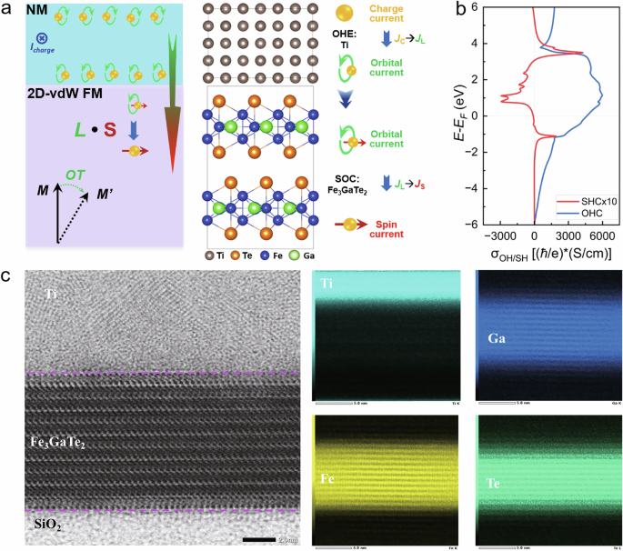
a Schematic of the Fe3GaTe2/Ti orbital torque heterostructure, in which the Ti orbital Hall material converts the charge current ( JC) into the orbital current ( JL), then the orbital current (JL) flows into the 2D-vdW FM Fe3GaTe2 layer and is converted into the spin current (JS) due to the spin-orbit coupling of the Fe3GaTe2 layer. b The calculated orbital Hall conductivity (blue line) and spin Hall conductivity (red line) of the Ti orbital Hall material. c The microstructure of the Fe3GaTe2/Ti heterostructure measured by the atomic-resolution scanning transmission electron microscopy (STEM).
Here, we selected Ti as the OHM and the 2D-vdW Fe3GaTe2 as the PMA FM layer to investigate the JC-to-JL-to-JS conversion and the OT-driven magnetization switching. The JC can be efficiently converted into the JL through the Ti OHM, which has a larger σOHE, calculated to be approximately 4600 (ħ/e)(S/cm). It is worth noting that, due to its weak SOC, Ti exhibits a negligible spin Hall conductivity (σSHE) of only about 11 (ħ/e)(S/cm), effectively ruling out the possibility of any significant SOT effect, as shown in Fig. 1b16. The JL generated in the Ti OHM layer can be efficiently converted into JS due to the strong SOC of the Fe3GaTe2 layer (see the right panel of Fig. 1a).
The Fe3GaTe2 possesses the hexagonal structure with two adjacent quintuple-layered substructures separated by a vdW gap, where each quintuple layer consists of a Fe3Ga heterometallic slab sandwiched between two Te layers, as illustrated in Fig. 1a. Fe3GaTe2 single crystal samples, grown by the self-flux method, exhibit high-quality crystallinity, as demonstrated by prominent (00 L) Bragg peaks (see Supplementary Fig. 1a) with an estimated Curie temperature of ~365 K (see Supplementary Fig. 1b and Supplementary Note 1for more details). Fig.1c presents the microstructure of the Fe3GaTe2/Ti (10.0 nm) heterostructure measured by the atomic-resolution scanning transmission electron microscopy (STEM). The crystalline structure of the layered Fe3GaTe2 and the high-quality interface of Fe3GaTe2/Ti are confirmed in the representative cross-sectional high-angle annular dark field STEM (HAADF-STEM) image of the Fe3GaTe2/Ti device. As shown in Fig. 1c, each layer of Fe3GaTe2 is constituted by the alternately arranged Te-Fe-Ga(Fe)-Fe-Te atomic planes. A polycrystalline Ti layer is uniformly sputtered on the Fe3GaTe2 layer, and the interface of Fe3GaTe2/Ti is flat and clean. Furthermore, through the corresponding X-ray energy dispersive spectrometry (EDS) map of the Fe, Ga, Te, and Ti elements, we observed the presence of sharp interfaces, indicating there is no obvious intermigration between the Fe3GaTe2 and Ti layers.
Orbital torque efficiency
To investigate the ξOT of the Ti OHM, the Ti (7–40 nm)/Ni (5 nm) samples were prepared and patterned into the devices with the size of 20 μm × 45 μm. Then the ξOT was measured by the ST-FMR methods (see details in Supplementary Note 2). In the ST-FMR measurements, the oscillatory resistance leads to a rectified mixing voltage (Vmix) due to magnetization precession coherent with the RF current41. Vmix is composed of VS and VA parts, where VS and VA represent the amplitudes of the symmetric and antisymmetric components which are proportional to the in-plane damping-like torque and out-of-plane torques, respectively. To exclude possible parasitic effects, the angular dependence of VS and VA is measured by sweeping in-plane external magnetic field (Hext) along with different directions (θ)41. The ξOT can be expressed as \({\xi }_{{{{\rm{OT}}}}}=({V}_{S}^{0}/{V}_{A}^{0})(\frac{e{\mu }_{0}{M}_{S}td}{\hslash }){[1+(4\pi {M}_{{{{\rm{eff}}}}}/{H}_{{{{\rm{ext}}}}})]}^{1/2}\), where ℏ is the reduced Planck’s constant, μ0 is the permeability of free space, MS is the saturation magnetization, t is the thickness of the Ni layer, d is the thickness of the Ti OHM layer, and Meff is the effective magnetization of the Ti/Ni bilayer. Fig. 2a, b and Supplementary Fig. 2 show the Vmix vs. Hext and angular dependence of VS and VA for the Ti (7–40 nm)/Ni (5 nm) devices. Through fitting row data, the ξOT is estimated to be 0.05–0.28 with an increase in the thickness of the Ti layer from 7 nm to 40 nm. These results demonstrate the dominant bulk OHE contribution from the Ti OHM layer in the Fe3GaTe2/Ti heterostructure. However, the interfacial orbital Rashba-Edelstein effect (OREE) contribution arising from symmetry breaking at the Fe3GaTe2/Ti interface cannot be entirely excluded due to experimental limitations in resolving opposing Oersted and field-like effect fields, which warrants further investigations.
Fig. 2: Orbital torque efficiency.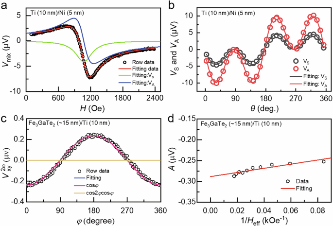
a The Vmix and the corresponding fitting VA and VS of the Ti (10 nm)/Ni (5 nm) device were measured by the spin-torque ferromagnetic resonance method under 8.5 GHz. b Angular dependence of VA and VS and the corresponding sin2φcosφ fittings for Ti (10 nm)/Ni (5 nm) device. c Azimuthal angle (φ) dependent second harmonic Hall resistance \({R}_{xy}^{2\omega }\) under Hext = 4.5 T of the Fe3GaTe2 (~15 nm)/Ti (10 nm) device measured by the harmonic Hall voltage measurement method. d The A value as a function of the 1/Heff by fitting \({V}_{xy}^{2\omega }-\varphi\) relations under different Hext.
To understand the physical mechanism of the magnetization switching, we fabricated the Fe3GaTe2 (~15 nm)/Ti (10 nm) devices, and then quantitatively characterized damping-like effective field (HDLy) and field-like effective field (HFLy) through the harmonic Hall voltage measurement (see details in Supplementary Note 2)36,42. When an alternating current is applied to the device, the OT drives magnetization oscillations at the frequency of the alternating current. Due to the nonlinear nature of the system, these oscillations generate a second harmonic Hall resistance\({R}_{xy}^{2\omega }\), described as:
$${R}_{xy}^{2\omega }=\left({R}_{{{{\rm{AHE}}}}}\frac{{H}_{{{{\rm{DLy}}}}}}{{H}_{{{{\rm{ext}}}}}+{H}_{{{{\rm{dem}}}}}-{H}_{{{{\rm{k}}}}}}+{R}_{{{{\rm{Ther}}}}}\right)\cos \varphi+\left(2{R}_{{{{\rm{PHE}}}}}\frac{{H}_{{{{\rm{FLy}}}}}+{H}_{{{{\rm{Oe}}}}}}{{H}_{{{{\rm{ext}}}}}}\right){{\mathrm{cos}}}(2\varphi )\cos \varphi$$
where RAHE, RPHE, RTher, HDLy, HFLy, Hext, Hdem, and Hk are anomalous Hall resistance, planar Hall resistance, resistance of thermal contributions from spin Seebeck effect, and anomalous Nernst effect, damping-like effective field, field-like effective field, external magnetic field, demagnetization field, and anisotropy field, respectively. For simplicity, the coefficients of cosφ and cos(2φ)cosφ terms are denoted as A and B, respectively, where \(A={R}_{{{{\rm{AHE}}}}}\frac{{H}_{{{{\rm{DLy}}}}}}{{H}_{{{{\rm{eff}}}}}}+{R}_{{{{\rm{Ther}}}}}\), \(B=2{R}_{{{{\rm{PHE}}}}}\frac{{H}_{{{{\rm{FLy}}}}}+{H}_{{{{\rm{Oe}}}}}}{{H}_{{{{\rm{ext}}}}}}\), and Heff = Hext + Hdem − Hk. Fig. 2c shows \({R}_{xy}^{2\omega }\) versus the azimuth angle φ under Hext = 4.5 T. By fitting the \({R}_{xy}^{2\omega }-\varphi\) relations under different Hext, we can obtain the 1/Heff dependence of A and the 1/Hext dependence of B, as shown in Fig. 2d and Supplementary Fig. 3d, respectively. By fitting A and B, we can obtain HDLy and HFLy of the Fe3GaTe2 (~15 nm)/Ti (10 nm) device. The corresponding damping-like torque efficiency ξDL is estimated to be ~0.26 following the equation of \({\xi }_{{{{\rm{DL}}}}}=(\frac{2{{{\rm{e}}}}}{\hslash }){M}_{S}{t}_{{{{\rm{FM}}}}}\frac{{\mu }_{0}{H}_{{{{\rm{DLy}}}}}}{{J}_{{{{\rm{Ti}}}}}}\), where MS, tFM, and JTi represent the magnetization, thickness of the Fe3GaTe2 layer, and the applied current density of the Ti layer, respectively. For the field-like torque ξFL, an accurate HFLy cannot be well fitted because RPHE is quite small (~10 mΩ) for our device. Thus, the ξFL is roughly estimated to be around ~ 0.06. These results reveal that both the ξDL and ξFL contribute to the magnetization switching, but the ξDL plays the dominant role. Therefore, it is likely that the JL generated in the Ti layer via the OHE is converted into the JS in the Fe3GaTe2 layer. Moreover, the JL can also exert a direct OT without the JL-to-JS conversion, governed jointly by the SOC and magnetic exchange coupling. This direct OT may exhibit long-range characteristics due to the crystal-field splitting induced orbital transport “hotspots” in momentum space15,43, which facilitate extended JL propagation. Both mechanisms are consistent with the observed dominance of damping-like torque, as they ultimately generate spin-polarized currents or orbital-derived effective fields that drive coherent magnetization rotation.
Orbital torque switching of 2D-vdW ferromagnet
To experimentally investigate the OT-driven magnetization switching, we fabricated the 2D-vdW FM Fe3GaTe2/Ti samples on the Si/SiO2 substrates, which were patterned into Hall bar devices (15 µm × 6 µm) (see the inset of Fig. 3a and Supplementary Fig. 4a) and characterized for current-induced magnetization switching through the OT (see the device fabrication and transport-property measurements in Methods). To assess the PMA of the Fe3GaTe2 (15.8 nm)/Ti (10.0 nm) Hall bar device, the room-temperature – anomalous Hall resistance (Rxy) vs. Hext loop was measured with both the in-plane and out-of-plane Hext, as shown in Fig. 3a and Supplementary Fig. 4b. The effective anisotropy fields (HK) were estimated to be 4.02–5.33 T as the temperature decreased from 300 K to 225 K, verifying a very strong PMA36,38,39. Meanwhile, the Rxy vs. out-of-plane Hext loops at even lower temperatures were measured to further characterize the PMA, as plotted in Fig. 3b. The Hall bar device demonstrates 100% remanence with well-defined rectangle Rxy vs. Hext loops. The coercivity (HC) of the Fe3GaTe2 (15.8 nm)/Ti (10.0 nm) Hall bar device increases from 19 mT at 300 K to 540 mT at 10 K, indicating very strong PMA. In addition, as the device was cooled from 300 K to 200 K, the value of Rxy increases from 4.7 Ω to 7.7 Ω, as plotted in Fig. 3c, suggesting the excellent magnetic properties of the 2D-vdW Fe3GaTe2 layer. In addition, there could be also a potential self-induced spin-orbit torque from Fe3GaTe2 that helps the magnetization switching. To check this point, we theoretically calculated the σSHC and experimentally investigated the magnetization switching of Fe3GaTe2. The results are shown in Supplementary Fig. 5. It is found that σSHC is calculated to be around 69, 95, 116, and 130 (ħ/e)(S/cm) for the monolayer, bilayer, trilayer, and bulk structures of Fe3GaTe2, respectively, which has negligible contribution compared to the σOHC of Ti [~4600 (ħ/e)(S/cm)] (see Supplementary Fig. 5a). Meanwhile, the magnetization switching of the single Fe3GaTe2 layer was not observed, as presented in Supplementary Fig. 5b. Therefore, the magnetization switching for the Fe3GaTe2/Ti device is primarily influenced by both the OT of the Ti OHM (σOHE,Ti) and the spin-orbital correlation strength of the Fe3GaTe2 layer.
Fig. 3: Orbital torque switching of 2D vdW ferromagnet.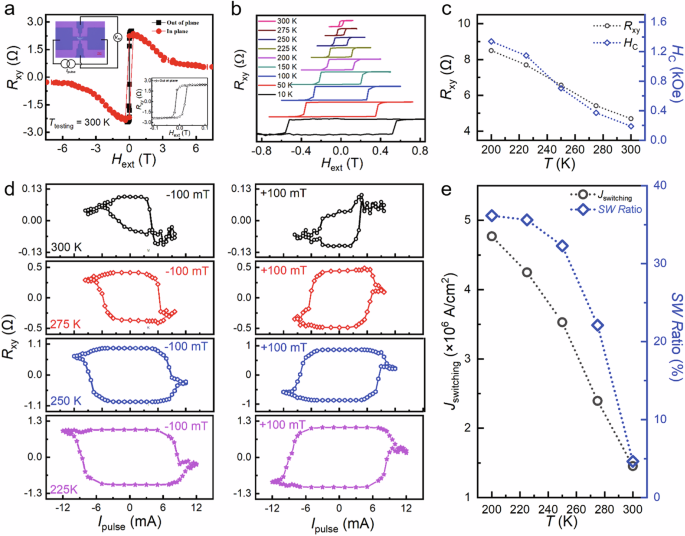
a The anomalous Hall resistance (Rxy) vs. the external magnetic field (Hext) loops measured at room temperature of the 2D-vdW Fe3GaTe2/Ti Hall bar device, where the Hext is applied along in-plane and out-of-plane directions. The insets show the image of the Hall bar device and the zoom-in out-of-plane Rxy vs. Hext loop. b The Rxy vs. out-of-plane Hext loops as a function of measuring temperatures of the Fe3GaTe2/Ti device. c The curves of the Rxy vs. Ttesting and the coercivity (HC) vs. Ttesting of the Fe3GaTe2/Ti Hall bar device. d The Rxy vs. the pulse current (Ipulse) loops of the Fe3GaTe2/Ti device measured with the in-plane Hext = ± 100 mT along the current direction at temperatures from 300 K to 225 K with the testing connection of I + – V + – I − – V − along the clockwise direction. e The Jswitching vs. T and the switching ratio (SW Ratio) vs. T of the Fe3GaTe2/Ti device.
To demonstrate the OT-driven magnetization switching of the 2D-vdW FM Fe3GaTe2 layer, the Rxy vs. the pulse current (Ipulse) loops of the Fe3GaTe2 (15.8 nm)/Ti (10.0 nm) Hall bar device were measured by applying the Ipulse with 1 ms write-pulse and a 6 s delay followed by read pulses (± 1.0 mA) under in-plane Hext ~ ± 20 mT – ± 150 mT applied along the current direction (see details in Supplementary Note 3). The experimental results are shown in Fig. 3d and Supplementary Figs. 6–8. Although the Curie temperature of the Fe3GaTe2 single-crystal sample is around 365 K (see Supplementary Fig. 1b), it will be slightly lower for the 2D-vdW FM Fe3GaTe2 thin film36. In this case, the PMA of the Fe3GaTe2 thin film can be easily decreased when the Ipulse is applied during the measurement of current-induced magnetization switching. Consequently, Rxy vs. Ipulse measurements were carried out at 300 K, 275 K, 250 K, and 225 K to ensure the FM state of Fe3GaTe2 with good PMA while studying the temperature-dependent magnetization switching behavior. Fig. 3d presents the Rxy vs. Ipulse loops of the Fe3GaTe2 (15.8 nm)/Ti (10.0 nm) Hall bar device measured with temperatures from 300 K to 225 K in the presence of a ± 100 mT in-plane Hext. The low resistance and high resistance states were observed at the measured temperatures when switching the Ipulse from positive to negative polarities. Reversing the direction of the in-plane Hext also resulted in a reversal of the polarity in the Rxy vs. Ipulse loops. Meanwhile, the ratio of magnetization switching exhibited an initial increase followed by a decrease as the in-plane Hext increased, as shown in Supplementary Figs. 6–8. This behavior excludes thermal effects and confirms that the 180° magnetization switching is driven by the OT from the Ti OHM. In addition, the Rxy vs. Ipulse loops of the Fe3GaTe2 (15.8 nm)/Ti (10.0 nm) Hall bar device become rectangle (see Fig. 3c) as the measured temperature decreased from 300 K to 225 K, suggesting the deterministic magnetization switching. Fig.3e shows the Jswitching and switching ratio as functions of temperature for the Fe3GaTe2 (15.8 nm)/Ti (10.0 nm) Hall bar device. It can be observed that the Jswitching gradually increases from 1.6 × 10⁶ A/cm2 to 4.8 × 10⁶ A/cm2 as the temperature decreases, attributed to the enhanced magnetic properties (e.g. PMA) of the Fe3GaTe2 layer as the temperature decreases. Notably, we observed that the switching ratio also increases as the devices are cooled. This enhancement may be attributed to the reduced thermal perturbation and the enhanced PMA of the Fe3GaTe2 layer at lower temperatures. The suppression of thermal fluctuations stabilizes a single-domain state, while enhanced magnetic exchange coupling promotes coherent magnetization alignment34. This enhancement may lead to an increase in direct OT generation governed jointly by the SOC and magnetic exchange coupling.
Orbital torque vs. spin-orbit torque
To further investigate the torque efficiency of OT, SOT, and the combined SOT + OT, we designed and prepared two additional samples: the SOT sample Fe3GaTe2 (18.3 nm)/Pt (5.0 nm) and the SOT + OT sample Fe3GaTe2 (16.7 nm)/Pt (2.0 nm)/Ti (10.0 nm). These samples were then patterned into the Hall bar devices (24 µm × 8 µm), all of which exhibit excellent PMA properties, as evidenced by their square Rxy vs. Hext loops. Subsequently, current-induced orbital/spin torque magnetization switching was performed under an in-plane Hext applied along the current direction (see Fig. 4, Supplementary Note 3, and Supplementary Figs. 9–12). Unlike the squared Rxy vs. Hext loops, the Rxy vs. the applied current density J loops do not always exhibit a perfectly squared signal measured at room temperature due to the thermal effect which resulted in magnetic moment disarrangement and PMA decrease. To ensure a fair comparison between different devices, we selected the Rxy vs. J loops measured at 275 K under an in-plane Hext = 100 mT, where all devices display near square-shaped Rxy vs. J loops. We note that the slight variation in Fe3GaTe2 thickness across different devices does not significantly affect Jswitching, as confirmed by our test measurements with various thicknesses. Fig.4a–c present the Rxy vs. J loops measured at 275 K of Fe3GaTe2 (18.3 nm)/Pt (5.0 nm), Fe3GaTe2 (16.7 nm)/Pt (2.0 nm)/Ti (10.0 nm), and Fe3GaTe2 (15.8 nm)/Ti (10.0 nm) Hall bar devices. Deterministic magnetization switching was observed in all devices, with Jswitching estimated to be approximately 9.2 × 10⁶ A/cm2, 5.9 × 10⁶ A/cm2, and 2.4 × 10⁶ A/cm2 for the respective devices. Notably, the Jswitching of the Fe3GaTe2 (15.8 nm)/Ti (10.0 nm) device is about four times smaller than that of the Fe3GaTe2 (18.3 nm)/Pt (5.0 nm) device, suggesting that the OT efficiency in the Fe3GaTe2/Ti heterostructure is higher than the SOT efficiency in the Fe3GaTe2/Pt heterostructure. For the combined OT and SOT effect, the Jswitching (5.9 × 10⁶ A/cm2) is higher than in the OT-only Fe3GaTe2/Ti device but lower than in the SOT-only Fe3GaTe2/Pt device. In addition, during current-induced orbital/spin torque magnetization switching measurements, the testing connection is I + – V− - I − – V + for the Fe3GaTe2/Pt device and I + – V + – I − – V − for Fe3GaTe2/Pt/Ti and Fe3GaTe2/Ti devices along the clockwise direction. In this case, although the Rxy vs. J loops present the same polarity shown in Fig. 4a–c, the OT- and SOT-driven magnetization switching has the opposite polarity due to the different testing connection, which further confirms the OHE of the Ti OHM in the Fe3GaTe2/Ti heterostructure and the SHE of the Pt SHM in the Fe3GaTe2/Pt heterostructure.
Fig. 4: Orbital torque vs. Spin-orbit torque.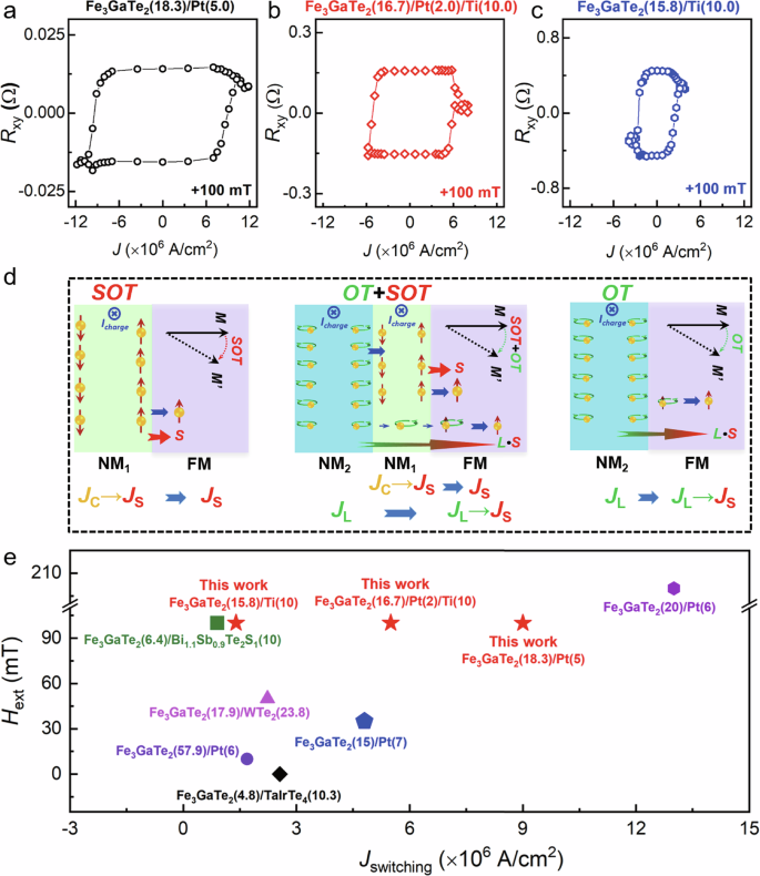
a–c The anomalous Hall resistance (Rxy) vs. the applied current density (J) loops measured at 275 K of the 2D-vdW Fe3GaTe2/Pt, Fe3GaTe2/Pt/Ti, and Fe3GaTe2/Ti Hall bar devices, respectively, under the in-plane external magnetic field (Hext) = 100 mT along the current direction, where the testing connection is I + – V− - I − – V + for the Fe3GaTe2/Pt device and I + – V + – I − – V − for Fe3GaTe2/Pt/Ti and Fe3GaTe2/Ti devices along the clockwise direction. d The physical mechanisms of the current conversion for the SOT, SOT + OT, and OT devices. e The summarized Jswitching values as a function of the in-plane Hext for 2D-vdW Fe3GaTe2 heterostructures driven through the SOT and OT at room temperature.
Figure 4d illustrates the possible physical mechanism behind the magnetization switching of these devices with different switching efficiency. For the Fe3GaTe2/Pt device, the JC directly converts into the JS in the Pt layer, the switching efficiency mainly depends on the SOT from the Pt SHM (σSHE,Pt), as shown in the left panel of Fig. 4d. However, for the Fe3GaTe2/Ti device, the switching efficiency is primarily influenced by both the OT of the Ti OHM (σOHE,Ti) and the spin-orbital correlation strength of the 2D-vdW FM Fe3GaTe2 layer. The JC first converts into the JL in the Ti layer, and then the JL is converted into the JS via the 2D-vdW FM Fe3GaTe2 layer, as presented in the right panel of Fig. 4. Considering the large OHE of the Ti, the significantly lower Jswitching of the Fe3GaTe2/Ti device compared to that of the Fe3GaTe2/Pt device indicates a rather strong spin-orbit correlation within the 2D-vdW FM Fe3GaTe2 layer. For the Fe3GaTe2/Pt/Ti device, the Pt SHM serves as an SOT source, and the Ti OHM acts as an OT source. The JS originates from two mechanisms: the JC-to-JS conversion through the Pt SHM and the JC-to-JL-to-JS conversation through the Ti OHM and the 2D-vdW FM Fe3GaTe2 layer. During this process, the Pt SHM converts not only the JC into the JS but also some of the JL from the Ti OHM into the JS42,44. The rest of JL from the Ti OHM may pass through the Pt layer and flow into the 2D-vdW FM Fe3GaTe2 layer, and then be converted into JS. The Pt layer may partially screen the JL flowing from the Ti OHM into the 2D-vdW FM Fe3GaTe2 layer, which diminishes the OT switching efficiency compared to that of the pure OT device, Fe3GaTe2/Ti. As a result, the Jswitching (~5.9 × 10⁶ A/cm2) of the Fe3GaTe2/Pt/Ti device falls between the values observed for the Fe3GaTe2/Ti and the Fe3GaTe2/Pt devices. We also summarize the Jswitching as a function of the in-plane Hext for the 2D-vdW FM Fe3GaTe2 devices measured at room temperature switched by the different SHMs and OHMs, as plotted in Fig. 4e. Very interestingly, the Jswitching of the Fe3GaTe2 devices switched via the light material Ti through OT is comparable to that of the Fe3GaTe2 devices driven by topological quantum materials through SOT [e.g. Bi1.1Sb0.9Te2S137, TaIrTe438, and WTe239]. This finding highlights the highly efficient conversion process of JC-to-JL-to-JS in the 2D-vdW FM Fe3GaTe2 layer, with potential implications for other 2D-vdW ferromagnets.
Spin-orbit correlation in the vdW ferromagnet
Based on the experimental results, we demonstrated that the Fe3GaTe2/Ti device exhibits high OT efficiency, as evidenced by its low JS, which arises from the contribution of both the Ti OHM and the 2D-vdW FM Fe3GaTe2 layer. The σOHE of the Ti OHM has been calculated to be ~4600 (ħ/e)(S/cm) (see Fig. 1b), making it one of the highest among OHMs. The ηL-S, which represents the strength of spin-orbit correlation \(\langle {{{\boldsymbol{L}}}}\cdot {{{\boldsymbol{S}}}}\rangle\) in 2D-vdW ferromagnets, is also expected to be significantly stronger. To verify this unique characteristic of the Fe3GaTe2, we chose the monolayer, bilayer, trilayer, and bulk structures for theoretical calculations, as shown in Fig. 5a. Comprehensive electronic simulations based on density functional theory were then performed to determine their spin-orbit correlation functions (see calculation details in the Methods and Supplementary Note 4). The FM ground state of the Fe3GaTe2 was adopted in calculations for all the structures. For the monolayer Fe3GaTe2, the magnetic moments are mainly located on the Fe-I (~2.38 µB) and Fe-II atoms (~1.41 µB), with small opposite contributions from Ga (~ −0.11 µB) and Te atoms (~ −0.09 µB) due to hybridization. Similarly, the bilayer, trilayer, and bulk Fe3GaTe2 exhibit a nearly identical distribution of magnetic moments as the monolayer Fe3GaTe2, due to the relatively weak vdW interaction between the layers. Further analysis of the orbital resolved band structure reveals that the majority of electronic states near the Fermi level (EF) are predominantly contributed by the 3d orbitals of Fe atoms, as illustrated in Fig. 5b for the monolayer Fe3GaTe2. The orbital-projected band structure of monolayer Fe3GaTe2 structure with different d states of Fe is highlighted by different colors when SOC is considered.
Fig. 5: Theoretical calculation of spin-orbit correlation function\({\langle {{{\boldsymbol{L}}}}\cdot {{{\boldsymbol{S}}}}\rangle }_{nk}\).
a The monolayer, bilayer, trilayer, and bulk Fe3GaTe2 structures, in which the Fe-I, Fe-II, Ga, and Te atoms are colored blue, light blue, green, and orange, respectively. b The orbital-projected band structure of monolayer Fe3GaTe2 structure with different d states of Fe is highlighted by different colors. c–f The calculated band-resolved spin-orbit correlation function \({\langle {{{\boldsymbol{L}}}}\cdot {{{\boldsymbol{S}}}}\rangle }_{nk}\) of the monolayer, bilayer, trilayer, and bulk Fe3GaTe2 structures, respectively. The color represents the correlation for each eigenstate, in which red and blue denote strong positive and negative correlations, respectively. Note that the Fermi energy is set to zero for reference.
The spin-orbit correlation \(\langle {{{\boldsymbol{L}}}}\cdot {{{\boldsymbol{S}}}}\rangle\) of the FM materials describes the conversion efficiency between the orbital (L) and the spin (S). Therefore, we calculated the band-resolved spin-orbit correlation function \({\langle {{{\boldsymbol{L}}}}\cdot {{{\boldsymbol{S}}}}\rangle }_{k,n}\) 9,45 and its integrated value, i.e., spin-orbit correlation coefficient \({\eta }_{L-S}={{\sum }_{{{{\rm{n}}}}}\int {{{{\rm{f}}}}}_{{{{\rm{k}}}},{{{\rm{n}}}}}\langle {{{\boldsymbol{L}}}}\cdot {{{\boldsymbol{S}}}}\rangle }_{{{{\rm{k}}}},{{{\rm{n}}}}}{{{{\rm{dV}}}}}_{{{{\rm{k}}}},{{{\rm{n}}}}}\) after constructing the effective Hamiltonian using the Wannier90 package46,47 (see Supplementary Note 4), where \({{{{\rm{f}}}}}_{{{{\rm{k}}}},{{{\rm{n}}}}}={{{\rm{f}}}}({{{{\rm{\varepsilon }}}}}_{{{{\rm{k}}}},{{{\rm{n}}}}})\) represents the Fermi-Dirac distribution of the nth band, and dVk,n denotes the momentum-space volume element, which takes a uniform Brillouin zone sampling. The calculated results of \({\langle {{{\boldsymbol{L}}}}\cdot {{{\boldsymbol{S}}}}\rangle }_{k,n}\) are summarized in Fig. 5c–f, in which red and blue colored areas denote strong positive and negative correlations, respectively. The positive value means that orbital angular momentum is converted to spin angular momentum in the same direction, and vice versa48. It is evident that positive/negative correlation hotspots appear near the EF (e.g., around the K and K1 points) corresponding to strong orbital-to-spin conversion efficiency. Further orbital analysis around these hotspots shows a significant hybridization of the 3d orbitals (dxy, dx2-y2, dz2), which leads to the large spin-orbit correlation, as shown in Fig. 5b\(\langle {{{\boldsymbol{L}}}}\cdot {{{\boldsymbol{S}}}}\rangle\) This is because the wave function that consists of dxy and dx2-y2 gives a larger matrix element’s value of the SOC operator \({{{\boldsymbol{L}}}}\cdot {{{\boldsymbol{S}}}}\)49. Note that these spin-orbit correlation hotspots occur in only one spin channel, which may further enhance the orbital-to-spin conversion during the OT switching process. Similar correlation hotspots can be observed for bilayer, trilayer, and bulk Fe3GaTe2 structures near the EF (especially near the K and K1 points), as plotted in Fig. 5d–f, confirming the robust spin-orbit correlation in Fe3GaTe2.
The spin-orbit correlation coefficient ηL-S was calculated to be around 0.375, 0.755, 1.153, and 0.762 for the monolayer, bilayer, trilayer, and bulk Fe3GaTe2 structures, respectively. The bulk Fe3GaTe2 structure contains two layers in the unit cell that are the same as the bilayer structure, leading to comparable ηL-S values between bulk and bilayer systems. This variation of ηL-S is due to the increased energy bands that contribute the \({\langle {{{\boldsymbol{L}}}}\cdot {{{\boldsymbol{S}}}}\rangle }_{k,n}\) blow the EF as the number of layers increases. Therefore, to compare the effective orbital-to-spin conversion efficiency in the monolayer, bilayer, trilayer, and bulk Fe3GaTe2 structures, we defined \({\eta }_{L-S}^{{{{\rm{eff}}}}}={\eta }_{L-S}/{{{\rm{N}}}}\) (N is the number of layers) to assess the spin-orbit correlation of each layer, which was estimated to be around 0.3752, 0.3773, 0.3842, and 0.3809, respectively, almost independent of the layer thickness. It is important to note that the 2D-vdW PMA ferromagnets are fundamentally different from traditional bulk PMA FM material due to their unique 2D-vdW nature. The switching of each magnetic layer could be much easier because of the robust thickness-independent \({\eta }_{L-S}^{{{{\rm{eff}}}}}\) and the rather weak interlayer coupling. While ηL-S/N is layer-independent in our model, practical efficiency is limited by the λOHE, beyond which additional layers do not contribute significantly. These results not only reveal the different JL-to-JS conversion mechanisms between the 2D-vdW ferromagnets and traditional ferromagnets but also provide insight into understanding the JL transport in the ferromagnets with unique 2D-vdW features.