
Device fabrication
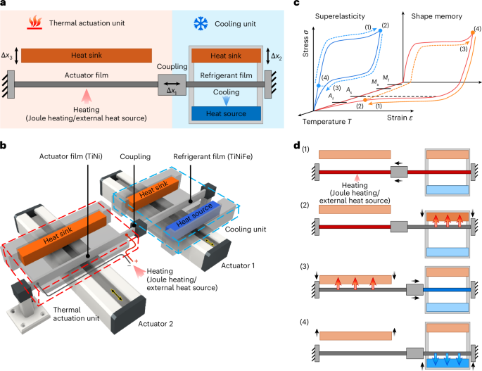
Detailed architecture designs of the prototype are provided in Supplementary Fig. 1. The heat sink in the actuation unit was mechanically cut from a 750-µm-thick Cu plate in a rectangular geometry (18 × 13 mm2). The surface was manually polished with polishing paper and metal paste to reduce contact resistance. It was attached to a 3D-printed cantilever structure to improve contact with the actuator film. The spring-like compliant cantilever mitigates film–heat exchanger misalignment and preserves stable thermal contact, even under minor buckling of SMA films.
The heat sink and heat source in the cooling unit were fabricated from 100-µm-thick Cu sheets by laser cutting into 7.0 × 0.5 mm2 strips. Surfaces were manually polished. A 350-µm-thick aerogel thermal insulation layer (Stanford Advanced Materials) was cut to the same size and adhered to the backside of the Cu heat exchangers. The performance of the insulation layer is shown in Supplementary Fig. 11, confirming its positive effect in maintaining heat exchanger temperature. The heat exchangers were glued to a polymethyl methacrylate (PMMA) support structure. A central hole in the PMMA allowed a miniature type-K thermocouple to be attached to the backside of the Cu sheet with thermally conductive glue. Polydimethylsiloxane (PDMS) square rings were placed around the PMMA support legs before assembly with the top and bottom PMMA plates to provide compliance. This design mitigates the effects of minor buckling in the refrigerant film and ensures stable, repeatable contact with the heat exchangers during operation. The heat sink and source were fixed 2 mm apart and moved together with the plates by an electromechanical linear actuator.
To clamp the refrigerant SMA films, PMMA blocks with a locating pin and hole ensured precise alignment. Two screws secured the films. For the actuator films, the bottom PMMA block was replaced with a PCB board to provide electrical connection for Joule heating. One side of the refrigerant film was clamped and screwed to a linear stage (Norelem; Supplementary Fig. 1, label A) for pre-straining at the beginning of operation.
The two SMA films were mechanically linked by a 3D-printed polymer coupler. The rigid structure ensured that the output force and stroke from the actuator unit were efficiently transferred to the cooling unit. Sliders mounted on the coupler guided motion along the longitudinal axis, reducing parasitic losses and concentrating the applied force. The polymer material and spacing of the coupler further provided effective thermal isolation between the two films.
Material fabrication and characterization
Ti50.18Ni49.82 and Ti49.1Ni50.5Fe0.4 films were fabricated by cold rolling at the University of Tsukuba, Japan, with 40% reduction to produce ~30-µm-thick films18,40. The TiNi films were heat-treated in a vacuum furnace at 450 °C for 30 min to obtain the one-way shape memory effect41. Samples were patterned by photolithography and HF–HNO3 wet etching. Actuator films were cut into 19.0 mm (active length) × 0.6 mm strips, followed by HF–HNO3 etching to remove oxides and thinned to 22 µm. The TiNiFe films were laser cut and electropolished (final thickness: 26.5 µm) at ADMEDES. The refrigerant film consisted of a 13.0-mm-long strip with ring-shaped ends, as shown in the inset of Fig. 2a. Each ring had an inner diameter of 1.0 mm and an outer diameter of 2.5 mm, providing precise alignment during clamping. The rectangular gauge section between the two rings was 7.5 mm long and 0.5 mm wide. Scanning electron microscopy images before and after electropolishing are provided in Supplementary Fig. 12, showing substantial surface improvement. A heat treatment at 500 °C for 30 min was required to obtain superelasticity at room temperature18.
Mechanical properties were measured by means of uniaxial tensile tests on a ZwickRoell Z0.5 testing machine. TiNiFe samples were trained for 20 cycles at a low strain rate (0.001 s−1) until their behaviour was stabilized. The TiNi samples were characterized in the martensite (23 °C) and austenite (83 °C) states in a temperature chamber. Polymer clamp extensions minimized heat loss and an additional thermocouple was attached near the sample to confirm test temperatures.
The fatigue behaviour of the superelastic TiNiFe refrigerant film was evaluated under tensile loading at 5.2% strain and a strain rate of 0.02 s−1. The film sustained more than 2,000 cycles without mechanical failure or observable functional degradation, confirming its mechanical robustness within the operating strain range of the present prototype. However, the primary objective of this work was to establish a proof-of-concept demonstration of heat-driven elastocaloric cooling rather than to optimize long-term cyclic lifetime. Consequently, fatigue-optimized SMA compositions were not specifically implemented in the current device. Notably, ultra-low-fatigue TiNi-based thin films have been reported in the literature. Ti-rich TiNiCu and TiNiCuCo films have demonstrated stable cyclic performance exceeding 107 cycles under tensile actuation without functional degradation42,43,44. These alloy systems are fully compatible with thin-film elastocaloric architectures. Combined with an improved mechanical design to minimize stress concentration and thermal accumulation, they provide a clear pathway towards substantially extending operational lifetime in future device generations.
IR thermography was performed with a FLIR A655sc camera at 50 fps (640 × 480 pixels, 17 µm pitch, maximum 200 fps). A black paint spray (emissivity: 0.97) was applied to SMA films before measurement. DSC was performed using a Netzsch Phoenix DSC 204 instrument at a heating rate of 10 °C min−1 across temperature ranges of −120 to 150 °C for TiNiFe and −100 to 150 °C for TiNi.
Device characterizationCharacterization of subsystems
The prototype was first evaluated at the subsystem level to isolate the performance of the actuation and cooling units.
In the actuation-only unit, TiNi films were Joule-heated under controlled pre-strain to study displacement and force generation. One end of the film was fixed, while the other was coupled to a TiNiFe superelastic film that functioned as a bias spring to enable cyclic operation. At the beginning of testing, both films were pre-strained with a force of 1.5 N, corresponding to a pre-strain length of 520 µm (ε = 2.7%) for the 19-mm-long actuator film. Joule heating pulses of 0.9–1.0 A with durations of between 90 and 180 ms were applied. Higher heating currents and longer pulse durations were not tested to prevent overheating of the actuator film and polymer clamping structures, as well as to avoid excessive heat accumulation that would prolong the subsequent cooling stage. With a pre-strain of 770 µm (ε = 3.2%), the shortest achieved loading and unloading cycle was 500 and 530 ms, respectively, using a 24 mm actuator film under 0.9 A and 90 ms pulses.
In the cooling-only unit, the thermal actuator was replaced with a precision electromechanical actuator to directly control the displacement of the TiNiFe refrigerant film. A second independent electromechanical actuator was used to cyclically move the heat sink and heat source, thereby modulating thermal contact and heat exchange. Strain amplitudes of 4–4.5% were applied at operating frequencies of 1, 1.33 and 2 Hz, with loading/unloading and holding times varied between 125 and 250 ms.
Device-level temperature spans were measured using miniature type-K thermocouples (tip diameter: 360 µm; sensing wire diameter: 80 µm) attached at the centre of the heat sink and heat source (denoted as TCmid in Supplementary Fig. 13a). To verify that TCmid accurately represents the overall heat-source temperature, an additional thermocouple (TCside) was placed near the edge of the heat source. The temperature difference between TCmid and TCside remained below 0.1 K throughout operation (Supplementary Fig. 13b), confirming a spatially homogeneous temperature distribution across the heat source during cycling.
Coupled heat-driven system with Joule-heated actuation
After subsystem evaluation, the actuator and cooling unit were integrated to form a coupled heat-driven system operated using Joule heating. In this configuration, the actuation stroke of the TiNi actuator film directly loaded and unloaded the TiNiFe refrigerant film via a polymer connector, ensuring thermal isolation while enabling efficient force transfer. The heat sink and heat source were cycled laterally into contact with the refrigerant film, while a second heat sink contacted the actuator film to regulate its temperature. A holding time of 0.5 s was applied during each thermal contact to allow sufficient heat exchange.
System control and data acquisition were carried out using a National Instruments cRIO-9067 CompactRIO controller running a custom LabView project. The force of the superelastic refrigerant film was measured using a U9C 100 N load cell (HBM; label B in Supplementary Fig. 1), and its axial displacement was recorded with a Panasonic HL-G103-S-J laser displacement sensor (label C in Supplementary Fig. 1). IR thermography was used to monitor the film-level temperature response, with carbon spray (emissivity: 0.77) applied to ensure uniform emissivity. Device-level temperature spans were acquired with miniature type-K thermocouples attached to the Cu heat sink and source. The input electrical power for Joule heating of the actuator was supplied by a GW Instek GPP-3060 DC power source, with pulse timing regulated by an external relay module controlled from LabView. Four-wire measurement was used to monitor the supplied electrical power. The electromechanical actuators used for the lateral motion of the heat sink and heat source of the cooling unit and the heat sink of the actuator unit were two servo linear actuators (ESR Pollmeier), operated via the EtherCAT protocol and logged through the CompactRIO system.
The integrated system was operated at a frequency of 0.83 Hz. The initial pre-strain of the actuator film was set to 520 µm (ε = 2.7%) and the Joule heating pulse was supplied with a current of 1.0 A with a duration time of 100 ms. This corresponded to a pre-strain force of 1.5 N, producing a pre-strain of ~50 µm in the refrigerant film. The pre-strain length was kept moderate as larger pre-strains did not improve cooling performance. It also prevented buckling of both SMA films during push–pull operation.
Under these conditions, a maximum material-level temperature change of 12.9 K and device-level spans of up to 4.0 K were achieved. The average heat-transfer times between the refrigerant film and the heat sink and heat source were approximately 270 and 350 ms, respectively, as determined from the temperature evolution of the heat exchangers. The experimentally derived thermal time constant (τ ≈ 62 ms) agrees well with the theoretical estimation (see Supplementary Note 3 for details). A stability test performed under Joule-heated actuation over 80 cycles (96 s) showed no degradation in temperature span or maximum loading force. Although a slight reduction in stroke was observed, the minimum value remained above the designed threshold of 300 µm, resulting in a stable cooling performance (Supplementary Fig. 14).
The material-level temperature change of 12.9 K for the TiNiFe films under Joule-heated thermal actuation is lower than the fully adiabatic value of 19.4 K measured under high-strain-rate tensile testing. This reduction arises from the limited strain rate during device operation. Similarly, the device-level temperature span of 4.0 K in the coupled heat-driven configuration remains below the maximum 8.2 K achieved in the cooling-only unit driven by an electromechanical actuator. In both cases, the limitation originates from thermally constrained actuation dynamics, which restrict both the strain rate and the achievable operating frequency. Fully adiabatic conditions typically require strain rates ≥0.1 s−1 ((un)loading velocity: ~750 µm s−1), whereas the present actuator provides 0.09 s−1 during loading (velocity: ~639 µm s−1) and 0.07 s−1 during unloading (velocity: ~526 µm s−1). These sub-adiabatic strain rates allow partial heat exchange during phase transformation. At the device level, the temperature span is further limited by finite heat-transfer rates between the refrigerant film and the heat sink/source, as well as by the thermal mass of the heat exchangers during cyclic operation. In the absence of regenerative or cascaded architecture15,45, the net temperature lift accumulated per cycle remains lower than the intrinsic material temperature change. Future improvements may focus on increasing strain rates through optimized actuator geometry, enhanced heat transfer or alternative actuation strategies to more fully exploit the intrinsic cooling potential of the refrigerant film. Advanced actuation concepts, including bistable configurations, agonist–antagonist designs or catch-and-release mechanisms46,47, together with multistage cascading architectures on the cooling side15,45, may further enhance the effective device-level temperature span.
CP was determined using both the temperature-slope method and direct counter-heating measurement. At zero temperature lift, the CPs obtained from the temperature-slope and counter-heating methods were 3.08 and 2.79 mW, respectively (Supplementary Fig. 7a and Supplementary Table 3). The close agreement between these values supports the reliability of the CP evaluation. The slightly lower value obtained from the counter-heating method is attributed to additional thermal leakage to the surroundings under finite temperature-span conditions during counter-heating operation. The COP values at zero temperature lift and exergetic efficiencies at −1.0 K temperature drop, derived using the CP from both methods under different input-power definitions, are summarized in Supplementary Table 4.
Coupled heat-driven system with external-heat-source actuation
The external heat source was fabricated in-house using a 5 × 5 mm2 platinum microheater (Innovative Sensor Technology). The microheater was bonded with thermally conductive adhesive to a 0.6-mm-thick Cu plate, which served as the contact interface with the actuator film. A thermocouple was attached to the Cu plate for closed-loop proportional-integral-derivative (PID) temperature control. A fin-structured Cu heat sink was employed to remove heat from the actuator film during the cooling stage.
The heat-source temperature was varied between 70 and 130 °C with a 250 ms contact time to determine the heating temperature (Ts) required to achieve sufficient loading stroke and acceptable loading/unloading times (Supplementary Fig. 9). The device operated in a four-step cycle, as illustrated in Supplementary Fig. 15. The operating frequency was set to 0.83 Hz, identical to that of the Joule-heated configuration, for direct comparison. The loading and unloading velocities were 507 µm s−1 (strain rate: 0.07 s−1) and 511 µm s−1 (strain rate: 0.07 s−1), respectively.
CP was determined using both the temperature slope and direct counter-heating methods. At zero temperature lift, the CPs obtained from the two methods were 1.36 and 2.09 mW, respectively (Supplementary Fig. 7a and Supplementary Table 3). The small difference between the two methods arises from their distinct evaluation principles. In the counter-heating method, the CP is inferred from the electrical power required to maintain thermal balance. Parasitic heat exchange with the ambient environment contributes to the applied heating power, which can lead to a slight overestimation of the CP48. In contrast, the temperature-slope method relies on the initial cooling rate of the heat source, which can be influenced by finite thermal response times associated with contact resistance and the thermal mass of surrounding components, resulting in a slight underestimation of the CP18. As a result, the two methods exhibit opposite systematic tendencies, leading to a difference between the evaluated values. The COP values at zero temperature lift and exergetic efficiencies at −0.5 K temperature drop, evaluated under different input-power definitions, are summarized in Supplementary Table 4.
Calculation of figures of merit
System performance was evaluated after 20 operating cycles, when the temperature span profiles reached steady state. The device-level temperature span is defined as the temperature difference between the Cu heat sink and heat source in the cooling unit, measured by type-K thermocouples.
CP and SCP were determined using two independent approaches: the temperature-slope method and direct counter-heating measurement. In the temperature-slope method, CP is obtained from the initial temperature decay rate of the heat source during the first cooling cycle at zero temperature lift18,49. In the counter-heating method, a calibrated 0.5 Ω NiCr resistance wire is used to electrically supply heat to the heat source until thermal balance is reached, and the electrical input power required to offset the cooling effect is taken as the CP. To establish controlled thermal loading conditions, the heat source was preheated using the resistance wire for 60 s before actuation. Subsequently, the elastocaloric system was activated to induce cooling, while the electrical heating was maintained throughout the measurement. The resulting temperature evolution under different thermal loads is shown in Supplementary Fig. 7b. All measurements were conducted during a run time of 24 s to ensure consistency with other tests throughout this work. The remaining temperature change rate at the end of the measurement was negligibly small and the temperature span development reached a steady state within the timeframe.
For the temperature-slope method, CP (\({\dot{Q}}_{{\rm{c}}}\)) is given by:
$${\dot{Q}}_{{\rm{c}}}={m}_{\mathrm{source}}{c}_{{\rm{p}},\mathrm{source}}{\dot{T}}_{\mathrm{source}}$$
(1)
where msource is the mass of the Cu heat source, cp,source is the specific heat of Cu and \({\dot{T}}_{{\rm{source}}}\) is the initial cooling rate of the heat source extracted from the first cooling cycle at zero temperature lift.
SCP (\({\dot{q}}_{{\rm{c}}}\)) is defined as:
$${\dot{q}}_{{\rm{c}}}=\frac{{\dot{Q}}_{{\rm{c}}}}{{m}_{{\rm{SE}}}}$$
(2)
where mSE is the active mass of the refrigerant film, determined from the clamped gauge length (7.5 mm). The numerical values of all parameters used in these calculations are provided in Supplementary Table 2.
COP was evaluated at zero temperature lift under different input definitions using the CP determined by both the temperature-slope and counter-heating methods. Exergetic efficiency (ηex) was evaluated at 50% of the maximum temperature drop (−1 K for Joule-heated operation and −0.5 K for external-heat-source-driven operation) using the CP obtained from the counter-heating method. Detailed definitions and formulations of COP and ηex under all evaluation criteria are provided in Supplementary Note 2, and a complete summary of efficiency values is presented in Supplementary Table 4.