
Key Takeaways:
When converting from air to liquid cooling, components without liquid may become too hot.
An entire board or system must undergo thermal analysis to ensure that any components that were once cool enough remain cool.
Alternative cooling techniques may be needed for components without liquid cooling.
Liquid cooling is proving effective at cooling high-power chips, such as GPUs, but it’s creating thermal issues for other nearby chips that previously benefited from the airflow used to cool those GPUs. With that airflow now gone, dissipating the remaining heat on PCBs is becoming a challenge.
Cooling keeps components running in spec, while fostering board and component reliability. “Temperature is always a leading indicator of reliability,” said Robin Bornoff, innovation roadmap manager at Siemens Digital Industries Software. “It doesn’t cause failure. It’s always a subsequent thermomechanical phenomenon. Something gets hot, so it bends, and if it bends too much, it breaks. And if it breaks, your C4 bumps (or whatever) fracture, and the whole circuit fails.”
Airflow reaches every part of a board, as does immersion cooling. More commonly, liquid strategically cools hot chips. Chips that do not qualify for liquid cooling may need additional passive or active cooling. This is giving rise to the notion of micro-cooling, in which cooling solutions target a limited space and cool only one or a few components.
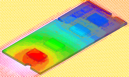
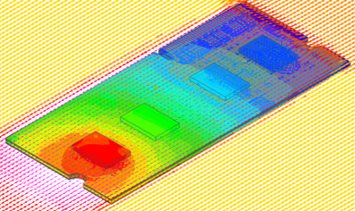
Fig. 1: This heat simulation of a board shows forced air coming from the upper right. If this changed to liquid, then the blue and red chips might be cooler, but the chips in between (if they didn’t receive liquid) may now be red. Source: Synopsys
Analysis of all components on the board is necessary to identify any new thermal issues in the absence of airflow. For such cases, alternate solutions do exist. “You do have alternative technologies like vapor chambers and heat pipes that can be implemented given a lack of active cooling,” said Jeff Tharp, senior product manager for Thermal Integrity in Electronics at Synopsys.
Basic thermal bookkeeping
Boards traditionally have been cooled as a single unit, with sufficient airflow to keep the components on the board operating within their specified temperature ranges. Determining airflow flux requires understanding all heat sources to ensure sufficient cooling.
“To establish the temperature value, you need to know the rate at which it’s produced and the rate at which it’s dissipated,” explained Tharp. “Where they come into balance establishes the operating temperature.”
But those boards typically have a few major heat generators and many other components. For purposes of this discussion, we can conveniently (if imprecisely) refer to chips that need liquid as hot chips, and those that don’t as warm chips if they’re closer to the heat limit and cool chips if they’re far from overheating. The focus tends to be on the hot chips, but when simulating the thermal performance of a whole board, contributions from other chips — warm or cool — will be included. And with air cooling, all components will see the benefit.
If the cooling analysis focuses only on the hot chips, the cooling method may be adequate for them but inadequate for the surrounding warm components. In the absence of air, warm chips may become hot chips. So does that mean they now must also be liquid-cooled? Perhaps, but not necessarily.
Whole-board interactions
The temperature at any given point on a board is a function of the heat being generated by various components and the means of dissipation. Generation generally depends on the component’s workload. That makes dissipation the practical knob to turn, since reducing the workload is a last-ditch measure that diminishes the utility of whatever function the board provides.
Dissipation can be affected by neighboring heat generators. An HBM stack sitting next to a hot GPU will have a harder time dissipating its own heat than it would without the GPU. Holistic analysis of the board should consider these component interactions to determine the appropriate airflow.
“When you’re doing temperature analysis, we can calculate how many watts the chip produces,” said Marc Swinnen, director of product marketing at Synopsys. “But watts is a rate. It’s not a temperature. And so the actual temperature at which that rate of heat production occurs depends on the environment. But it’s a bit of a chicken-and-egg thing because the wattage of the chip depends on its temperature, but the temperature depends on the wattage, so you have to iterate a few times.”
The critical question then becomes whether all cooling is bespoke for a given board, or whether some chips are purchased with cooling already in place. A chip designed for liquid cooling may have the cooling installed in isolation during manufacturing. Techniques such as cold plates can be installed during board assembly and tailored to the specific board, but direct impingement, for example, requires unimpeded access to the silicon die. That can’t be attached after the fact without exposing the silicon to damage or impurities between the fab and the assembly house.
In those cases, the cooling may be installed solely based on the heat characteristics of that chip, ignoring the effects of surrounding components. When someone purchases such a device for installation, they can rest assured that the chip will remain in spec, but it says nothing about neighboring components.
Additional cooling options
Board thermal analysis can identify components that aren’t liquid-cooled, but which are now at risk of overheating. In that case, cooling techniques fall short of full-on liquid cooling. “There are still a lot of technologies out there to utilize in the absence of forced airflow,” noted Tharp.
Some of those techniques involve liquid, but in a self-contained form. Examples include vapor chambers and heat pipes.
Vapor chambers exploit convection in a small volume to allow liquid to touch the top of the chip’s package. The liquid evaporates and rises to the top of that volume, where it interacts with an external cold plate that cools the vapor back down into a liquid. Convection keeps the liquid and vapor moving for effective heat removal.
Heat pipes look almost like liquid cooling. They use liquid, too, but they lack the extensive cooling infrastructure that full-on liquid cooling requires. It’s almost like a mini-liquid-cooling setup. The idea is simply to take the heat from a chip — especially one in a crowded area with little room to add anything — and move it elsewhere for more effective dissipation. The movement is driven by the generated heat, so this isn’t a perpetual-motion machine.
“Inside is a coolant that, when it picks up the heat on the evaporator side, changes phase into vapor,” said Satya Karimajji, senior engineer, SoC engineering at Synopsys. “It moves from the evaporator to the condenser. In the condenser, you have a heat sink or a fan that takes the heat away from that vapor, and then it condenses, and that is sent back to the package [via capillary action].”
Some of these techniques were invented for different sorts of systems. “Heat pipes and vapor chambers are used in low-profile applications like laptops or phones,” said Karimajji. But they may broaden their reach.
Some cases may not require such an elaborate setup. Heat sinks typically remove heat through airflow, but even without airflow, a well-designed heat sink improves cooling by providing greater surface area for heat dissipation.
Local fans
Where board space allows, some engineers will insert small fans onto the board to provide additional airflow. Such fans may occupy a nontrivial amount of space, and their positioning is critical to ensuring proper airflow over the components of concern. If moving that air outside the board is sufficient, then this could work. But if the air needs to be further evacuated from outside the board, this requires adding back the air infrastructure removed during the conversion to liquid.
Rotary fans tend to be bulky and, while a small version might work on a board, they would never fit into systems with extreme space constraints, such as smart glasses. They also tend to be noisy.
One alternative involves placing a MEMS (micro-electromechanical system) unit atop warm chips to act as a miniature fan. Such a unit has two ports, one for letting air in and another for forcing it out. Mounted atop a chip package, a standoff region provides space for airflow between the fan and the chip, or a side-vented model allows mounting on the chip without a standoff.
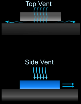
Fig. 2: Two ways of placing a MEMS fan atop a chip. In the top version, a standoff leaves room under the chip for air to move out sideways, or even up and out the top vent. With a side vent, no standoff is needed. Source: xMEMS
Such a unit from xMEMS has evolved out of the company’s speaker business. MEMS speakers tend to exploit the piezoelectric effect, using a signal’s varying voltage to move a diaphragm, which in turn moves air. We perceive moving air as sound. “We’re using piezo as our actuator, and silicon is our diaphragm,” said Mike Housholder, vice president of marketing and business development at xMEMS. “Depending on the resonant frequency of how we drive the MEMS and how we modulate the ultrasound, we can either produce audio or we can also produce airflow.”
That same idea can produce a fan that runs at a constant or even variable speed, but without the modulation a speaker would provide. An accompanying ASIC chip drives the piezo element to vibrate, and that vibration moves air through a port. Air can move in either direction — in the bottom and out the top, or vice versa. For instance, one could run it in one direction for cooling and the opposite direction for cleaning.
“The system processor sets the airflow direction in the ASIC via I2C commands,” said Housholder. “Airflow direction can be changed on the fly, and the airflow rate can be dynamically adjusted in real time. Airflow is voltage-controlled. Turn the voltage up, more airflow; voltage down, less airflow.”
Quieter than typical fans
Given the audio provenance of this technology, it’s notable that frequencies are in the kilohertz range, typically far below the frequencies of any components on the board. It would take extraordinarily high overtones to interfere with anything electrical. And with six or more orders of magnitude between the fan frequency and the chip frequencies, the gap is too large to entertain overtones of any discernible power.
Another complaint about fans is the noise they make. Humans hear in the kilohertz range, but this fan operates at over 40 kHz, which is twice the top frequency typically ascribed to humans. That keeps it quiet.
“There is no mechanical noise at 3 centimeters,” said Housholder. “Our noise signature, which is just air flow, is 18 dBA. It’s inaudible.” (dBA is decibel level weighted for the response characteristics of the human ear. For comparison, a soft whisper is around 30 dBA.) The company also claims they’re impervious to interference from outside vibrations.
Additional steps may be necessary to ensure the air reaches the right places. “In the example of an SSD [an application the company supports], we use a metal shield — kind of like an EMI shield for RF,” said Housholder. “It could be plastic — the materials don’t matter. We’re channeling the airflow through all the chips underneath that shield. Depending on how you duct it or channel it, we can pull cool air in from outside or somewhere else in the system.”
xMEMs is looking into cooling HBM stacks with this, but it can’t add to the top of the stack. A possible alternative is to cool the sides. That could help the middle dies in a stack, which are the most difficult to cool.
MEMS coolers can be mounted on a chip or on the board. The company could even make one as a chiplet to be installed in an advanced package. For that to work, however, it would need to change from a metal lid to a silicon cap, and the advanced package would require intake and outlet ports.
Active heat sinks
The company is also exploring what it calls active heat sinks, mounting the fan atop a heat sink. Most heat sinks must leave enough space between fins or pins to allow normal airflow. This gets to the notion of backpressure, which indicates how much push-back there is against the flowing air. For a conventional fan, it’s low, but for a micro-fan, it’s much higher since it blows directly onto the top of the heat sink. That means the heat sink could use a denser pin array to increase surface area and thus improve heat removal.
“We use our backpressure to our advantage to move air through small spaces,” explained Housholder. “It’s very directed cooling to a particular hot spot, whereas a fan is more a broad blast of airflow.”
The size is 9 × 7mm2, with a thickness of 1mm. Costs are in the range of $5 to $10. They were originally designed for smartphones and AR glasses, which may accommodate that price, but it may be a tougher sell for consumer items, some of which are getting hotter. Their first foray into the data center is within solid-state drives (SSDs).
It works only for components with moderate heat generation. “Micro-cooling can make an impact on systems up to 15 to 18 watts,” said Housholder. “This is dependent on the specific system thermal architecture.”
Some uncooled chips need cooling
Given a conversion to liquid cooling — or even if uncooled systems evolve to the point of requiring some cooling — a full-board analysis is necessary to identify the hot, warm, and cool chips.
Hot chips use liquid immersion in data centers. Outside the data center, one is unlikely to encounter liquid-cooling infrastructure, so a microfan can help cool hot chips that consume up to ~20 watts, given current technology. Above that, and absent true liquid, steps must likely be taken to reduce heat generation if airflow is insufficient.
Warm chips that previously required no extra cooling may now require heat sinks, vapor chambers, heat pipes, or localized fans. The cool chips will warm up, but they still should operate in their intended range.
As more systems transition to liquid cooling and power levels rise, additional options may well emerge for chips that need help but don’t require full-on liquid cooling. Regardless of the cooling options available at any given time, a full board analysis will always be necessary to deploy them.
Related Articles
Cooling Chips Still A Top Challenge
Heat pipes, lids, thermal interfaces, and micro-channel cooling help remove the heat generated by chips.
How To Cool 3D-ICs
Tool chains need improvement as chipmakers begin stacking AI chips, increasing the thermal density and unpredictability over time.
Liquid Cooling Gains Traction In Data Centers
There are numerous ways to remove heat from chips, and more are on the way.