
Shortly after the free-electron laser (FEL) concept was proposed in the 1970s11, the first FEL oscillator was developed12 and many such systems were soon in operation worldwide in the infrared to ultraviolet wavelength regime13, where high-reflectivity mirrors were well established. Lacking suitable cavity optics, hard X-ray FELs adopted single-pass, high-gain self-amplified spontaneous emission (SASE)6. However, SASE radiation shows significant shot-to-shot fluctuations and is limited in longitudinal coherence compared with visible-light lasers, with typical bandwidths of ≥0.1% (ref. 14). A significant improvement has been achieved with the self-seeding technique15,16,17,18,19, where a crystal in Bragg reflection is inserted after an initial undulator section and the diffracted, filtered radiation is then used to seed a new lasing process in the downstream part of the undulator. This improves spectral purity and spectral flux, yet it does not fully address stability and coherence limitations. An X-ray laser oscillator was proposed20 that exploits stimulated emission from atomic inner-shell transitions21,22,23 within an X-ray optical cavity pumped by an X-ray free-electron laser (XFEL) beam, but a complete X-ray laser oscillator has not yet been realized.
As an alternative approach, cavity-based XFELs (CBXFELs)7,8,9, including both high-gain regenerative X-ray amplifier FELs7 and low-gain XFEL oscillators8, trap and monochromatize X-ray pulses in a Bragg-reflecting cavity around only a few undulator segments and synchronize them to high-repetition-rate electron bunches. This oscillator scheme has the potential to generate fully coherent, highly stable and spectrally pure X-ray pulses analogous to the infrared/ultraviolet oscillators, while reducing the requirement for very long undulator lines10,24,25,26,27,28,29,30,31,32,33,34.
Realizing such a device requires accelerators with sufficiently high peak brightness, capable of delivering at least tens of electron bunches at a repetition rate high enough to confine the cavity length to a practical scale of several tens of metres5,35. Owing to their exceptional thermal characteristics and high reflectivity, diamond single crystals are uniquely suited as Bragg reflectors for this application36. Still, there are considerable technical challenges to overcome to realize such a cavity in an accelerator environment, as it requires stability and alignment tolerances at the nanoradian level, while adjusting the overall length of the cavity to micrometre accuracy37.
Recently, low-loss ring-down of X-rays in a diamond-based cavity without undulators was demonstrated at the Linac Coherent Light Source38, showing the feasibility of the X-ray optical requirements, but no FEL amplification.
Here we report on the demonstration of lasing in an X-ray cavity with intra-cavity undulators10. A schematic of the experimental set-up is shown in Fig. 1. The last 4 segments with 20-m active length of the European XFEL SASE1 undulator line were used at an electron energy of 14 GeV. The undulator segments are enclosed by a pair of retro-reflecting units at a distance of 66.41 m (cavity path length 132.8 m), each consisting of 1 diamond crystal and 2 perpendicular X-ray mirrors. The cavity length was fine-tuned to the electron bunch repetition rate of 2.23 MHz by translating the downstream unit. As intra-cavity diagnostics, an X-ray transmission grating was inserted into the beam path that diffracts a small fraction of the beam onto a photodiode. In addition, a transmissive scintillating screen, a single-shot spectrometer and an X-ray gas monitor located downstream of the cavity were used to monitor the outcoupled X-ray pulses. Details of the set-up and alignment procedure are described in Methods. A list of the most important parameters is given in Extended Data Table 1.
Fig. 1: Experimental set-up.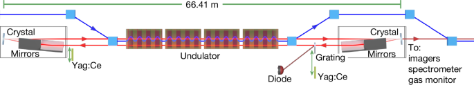
Schematic of the CBXFEL experiment at the SASE1 undulator line of the European XFEL. The X-ray cavity consists of two diamond crystals in Bragg reflection working close to backscattering geometry and two pairs of focusing X-ray mirrors to steer and focus the beam. The surfaces of the crystal and the mirrors are perpendicular to each other, forming a retro-reflector. The elements in the retro-reflector are aligned such that the beam after reflection returns at a distance of 2.67 mm from the incident beam inside the same vacuum pipe. The downstream retro-reflector unit (on the right) can be translated to tune the cavity length. The electron beam (blue) is injected from the left using a magnetic chicane, and the X-ray pulse (red) is circulating in the cavity, overlapping with electron bunches that pass the undulator at 2.23 MHz. A retractable transmission grating extracts a fraction of the circulating X-rays for diagnostics. Cerium-doped yttrium aluminium garnet (Yag:Ce) scintillating screens can be inserted at both sides of the cavity for photon alignment.
First, the cavity was spatially aligned to a condition, where a ‘cold’ ring-down of individual pulses in the cavity can be observed (Fig. 2, orange curve). In this case, trains of 100 250-pC electron bunches at a repetition rate of 2.23 MHz were injected into the cavity. Without matching the cavity length, no amplification occurred, and the radiation from a single pass of electrons through the undulator was bouncing inside the cavity, without interaction with further electron bunches. With femtosecond synchronization and micrometre-scale transverse overlap of the electron bunches and the recirculating, monochromatized photon pulses, they seed the successive electron bunches, thereby increasing photon production within a narrow bandwidth. To achieve this synchronization, the length of the spatially aligned cavity was scanned on the micrometre-scale while monitoring the pulse energy of the recirculating photon pulses using grating-based in-cavity diagnostics as well as the spectrometer and the downstream transmissive imager. In Fig. 3, the cavity length variation is shown on the vertical axis and the horizontal axis shows the recirculating pulses. When the cavity length matches the repetition rate of the electron bunches, a strong increase of the spectrometer signal from bunch to bunch is observed. This was accompanied by a strong rise in signal on the downstream transmissive scintillator as well as saturation of the in-cavity diagnostics (Extended Data Fig. 1). The apparent dependence on the cavity length is conclusive evidence that the oscillator lasing condition has been achieved.
Fig. 2: Photodiode ring-up and ring-down traces.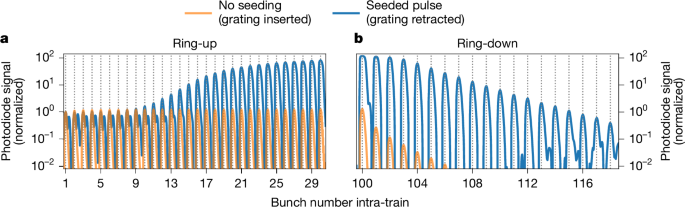
a,b, Baseline-corrected photodiode traces averaged over 1,000 pulse trains showing ring-up (first 30 pulses) (a) and ring-down (pulse at the last electron bunch and 20 pulses after) (b) of the seeded (blue) X-ray pulses. The pulses are normalized to the peak of the first bunch. The vertical dotted lines indicate the bunch number. For comparison, the signal without seeding is shown in orange. The actual photodiode signal of both traces are not comparable, as the orange curve was taken with grating inserted and the blue one with grating retracted (98% lower base signal for the blue curve; Methods). For the blue curve, the first bunches show a double peak structure, where the second peak is caused by the subsequent electron bunch passing by. The Δt ≈ 267 ns separation between the minor and the next dominant peak corresponds to the round-trip light path to the downstream crystal and back to the photodiode. This is only visible owing to the lower base signal of the blue curve. For the ring-up and the pulses 101 to 103 in the ring-down, the blue curve is affected at large signal rates by detector saturation, showing as a flattening of the peaks. In the ring-down, the orange line has additional losses due to the grating.
Fig. 3: Cavity resonance scan.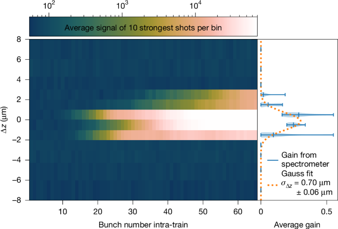
Trace of the peak spectrometer signal on a logarithmic scale during a longitudinal cavity scan with 1-μm step width. Per step, the average of the ten most intense trains is shown. The x axis shows the bunch number within an electron bunch train, with the bunches having a 2.23-MHz spacing; the y axis shows the cavity delay detuning Δz. Near resonance (Δz ≈ 0), an orders-of-magnitude increase in the spectral signal is visible, indicating lasing. Off-resonance, a three-orders-of-magnitude-weaker and stable signal without gain is observed. On the right, the calculated round-trip gain (Methods) is shown as a violin plot over the ten samples per step. The Gauss fit shows that seeding occurs over a longitudinal range of σz = (0.7 ± 0.06) μm.
Figure 2 shows the ring-down of the diode signal in seeding condition (blue curve, grating retracted) as well as for the cold-cavity case (orange curve, grating inserted). From these curves, the cumulative cavity reflectivity for a single round-trip is estimated to be 67.3(4)% for the case with seeding and 75% for the cold cavity (corrected for the grating losses). This is significantly lower than the theoretical combined peak reflectivity of 96.8%. As discussed in literature39, such differences can be attributed to imperfections in the optical components, such as strain in the crystals that reduce the peak reflectivity. In addition, wavefront distortions introduced by the imperfections of mirrors and crystals lead to higher cut-off losses at the finite-length mirror apertures. In addition, imperfect alignment of the mechanics can lead to stronger losses38. However, this effect is suspected to be small, as the cavity was aligned by maximizing the ring-down signal. In the simulation (Methods), the ring-down is already reduced to 85% by including the finite size of the mirrors and their measured imperfections.
Spectra in lasing condition taken downstream of the cavity are shown in Fig. 4. The photon spectrum generated by the first bunch shows a very broad distribution with a bandwidth of EFWHM = (21 ± 6) eV full-width at half-maximum (FWHM), corresponding to a unsaturated SASE spectrum from a single pass. The later bunches, exemplarily shown for the 65th as the last one measured by the spectrometer, produce much narrower and more intense spectra as a result of the seeding from the recirculating photon beam in the cavity. The inset in Fig. 4 shows that the seeded spectrum has a certain asymmetry. This can be understood from the very simple outcoupling mechanism used in this demonstrator set-up: instead of using a dedicated outcoupling mechanism (for example, as proposed in refs. 28,30,40), the photons transmitted through the downstream crystal were monitored7,10. The central part of the spectrum is reflected inside the cavity (see green dotted curve in Fig. 4). Therefore, only the wings of the spectrum generated by a single pass through the undulator are transmitted in this scheme. This leads to a double-hump structure in the spectrum of the transmitted pulse. Owing to the limited resolution of the spectrometer, which is σE ≈ 60 meV rms (Methods), it appears here as an asymmetric curve of FWHM EFWHM = (0.24 ± 0.06) eV.
Fig. 4: Spectral profile narrowing.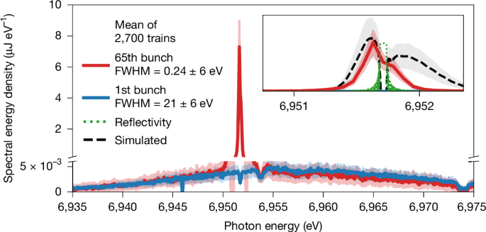
Spectra taken downstream of the cavity set-up. The main panel shows the spectrum generated by the 1st bunch in blue and by the 65th bunch in red. The y-axis scale is broken to highlight both high and low spectral energy densities. The dip in the blue curve at a photon energy Eph = 6,951.7 eV is caused by the reflection of the downstream crystal. The dip to its right is caused by another diamond-based beamline component. The inset emphasizes the spectrum of the 65th bunch with a zoomed-in view. The green dotted line in the inset shows the calculated, idealized reflection curve of the downstream crystal. The black dashed line in the inset shows a sample simulation curve based on the experimental parameters (Methods). The more pronounced right wing of the simulated curve can be traced back to a difference in electron phase space between simulation and experiment.
By referencing the spectrometer to a calibrated gas-based X-ray pulse energy monitor41 downstream of the set-up, the per-pulse energy evolution can be determined. The maximum pulse energies measured during a pulse train range from 4 μJ to 13 μJ, varying from train to train, with an averaged observed gain \(\bar{{\mathcal{G}}}\) per round trip of 0.4 (Methods and Extended Data Fig. 2b). Considering that only the outcoupled fraction is measured, one can expect the number of photons stored inside the cavity to be higher, by an amount varying with the evolution of the intensity10,39 and not quantified during this experiment. Limitations of the current set-up by heat load effects are shown in Fig. 5, where the integrated spectrum of the outcoupled photon pulse was measured with the spectrometer as a function of bunch number. In this case, the diagnostic grating was retracted to maximize gain. One can see that for three sampled individual bunch trains, the pulse energy reaches a maximum, then decays and oscillates back to some average value. Owing to the long oscillation period over multiple bunches, this cannot be explained by shot-to-shot fluctuations in the beam quality. Also, saturation of the FEL process is expected at much higher pulse energies at around 1 mJ (refs. 10,39). Compared with the simulation (see the black dashed line) and as discussed in the literature10,25,39,42,43, this can be attributed to heat load effects on diamond crystals, which affect the FEL process in two ways. First, the non-homogeneous temperature distribution leads to heat bumps on the lattice, decreasing the overlap of the reflected photon pulses with the electron beam. Second, the seeded and intensified incident X-rays lead to different temperature drifts for both crystals in the range of a few kelvin during a pulse train. At some point, the lattice constants are too different because of thermal expansion and the reflection curves of the two crystals do not overlap anymore. Then the photon field decays, resulting in a temporal decrease of heat load and, thus, to a response loop causing the pulse energy to oscillate. As shown in simulations10,39,42, this effect can be strongly reduced by cooling the diamond crystals to cryogenic temperatures, bringing about a significantly higher photon output. However, with the current set-up, the anticipated increase in thermal load will probably also cause instabilities in the low-temperature regime10.
Fig. 5: Intra-train intensity evolution.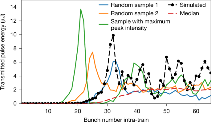
Evolution of integrated spectrum versus bunch number. The different colours indicate individual sample trains. The different onsets and maxima of the curves are owing to the different gain varying from train to train. The dashed red curve shows the median signal per intra-train bunch number over the 2,700 trains in the dataset. It shows much smoother behaviour as the oscillations are mostly washed out by the statistics. The dashed pointed black line is an exemplary simulation with the parameters taken from the experiment (same as in Fig. 4). Extended Data Fig. 2a shows the statistical distribution of the pulse energy taken over 2,700 trains in the dataset.
In conclusion, we have demonstrated lasing with multi-pass gain in a CBXFEL. This achievement provides definitive experimental proof of concept for CBXFELs, two decades after their initial theoretical proposal7,8. Our results establish the feasibility of synchronizing a 132.8-m X-ray cavity with 2.23-MHz-repetition-rate electron bunches, overcoming challenges in alignment, stability and synchronization.
The observed X-ray pulses show high spectral purity and narrow bandwidth, confirming the key theoretical predictions7,10, and demonstrate the potential of CBXFELs to deliver fully coherent X-ray radiation in a relatively compact assembly. Although the current proof-of-concept set-up has not yet reached the peak intensities of state-of-the-art SASE or self-seeded XFELs, significant improvements are expected through further optimization of electron beam and cavity parameters, cryogenic cooling of the crystals10,42, and advanced outcoupling schemes30,44. Simulations suggest a ten- to hundred-fold increase in pulse energy up to millijoule levels and an increase of up to three orders of magnitude in spectral flux, surpassing the capabilities of self-seeding and SASE10,28,30,39. Further experiments are planned to investigate this.
This demonstration of X-ray lasing in a cavity opens the path towards next-generation X-ray sources with unprecedented coherence, stability and spectral brightness. The CBXFEL concept enables transformative experiments such as millielectronvolt-resolved inelastic and nuclear resonance spectroscopy45, ultrafast pump–probe resonant inelastic X-ray scattering46 in the hard X-ray regime, and nonlinear wave-mixing47,48, while unlocking regimes in quantum X-ray optics49. These capabilities not only expand the frontiers of X-ray science but also motivate more compact and user-friendly facilities delivering high-coherence beams to a broader experimental community.