
Concept of nonvolatile twisted MTJ
CrSBr is an A-type AF van der Waals (vdW) n-type semiconductor with a paramagnetic (PM)-to-AF transition at ~130 K (Néel temperature, TN) and a substantial intralayer FM coupling evolving at a characteristic higher temperature (TC, ~150 K)22,23,41,42. CrSBr crystallizes in the orthorhombic space group Pmmn with crystal axes a ≠ b ≠ c and exhibits a strong magnetocrystalline anisotropy, such, within the ab plane, the easy axis lies along the b-axis and the hard axis is aligned along the a-axis. The uniaxial in-plane magnetic anisotropy and intralayer FM coupling are robust down to the monolayer limit, and the interlayer AF coupling is robust down to the bilayer limit42,43,44. The semiconducting properties and unique magnetic characteristics make CrSBr an ideal platform for exploring 2D twisted MTJs37,38,45,46,47.
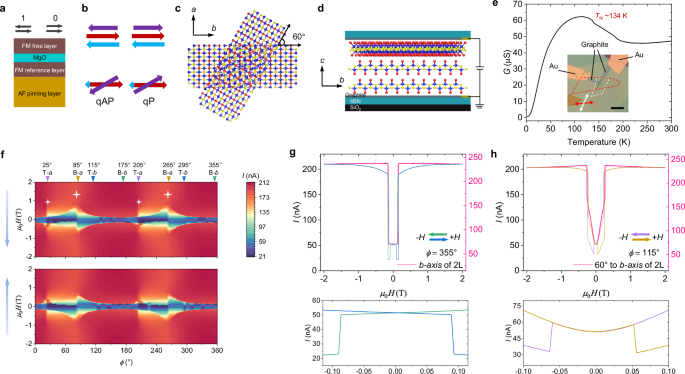
The top panel of Fig. 1b shows a 3-layered stack that can be viewed as an assembly of a natural CrSBr bilayer (blue and red arrows) and a top CrSBr monolayer (purple arrow), in which two interfaces are formed. By setting the top monolayer at an angle relative to the bottom bilayer, a top twisted interface can be formed with a twist angle, θtwist (bottom panel of Fig. 1b). At ZF the spin configuration is always antiparallel in the lower untwisted interface because of the strong interlayer AF exchange interaction from the linear superexchange chain of Cr-Br-Br-Cr across the vdW gap in the natural CrSBr system37. By contrast, the spin configuration at the upper twisted interface has bistable states at ZF, quasi-antiparallel (qAP) and quasi-parallel (qP), due to the negligible magnetic coupling across the twisted interface since a twist with a large θtwist considerably tilts the Cr-Br-Br-Cr superexchange chain37. Meanwhile, a twist with a large θtwist can suppress the formation of moiré superlattices observed in twisted magnets with small θtwist (usually less than 10°)48,49,50,51,52. The prefix “quasi” denotes that the parallel and antiparallel configurations are not aligned perfectly but rather are misaligned via an acute angle (θtwist for qP) and an obtuse angle (π − θtwist for qAP). The final tunneling conductance (G) of this twisted 3-layered stack is proportional to the product of electron transmissivity (Ti) at each interface (\(G\propto {T}_{1}{T}_{2}\)) due to a spin-filtering mechanism37,53, whose magnitude is related to the relative angle (θi) of the spins at the ith interface, \({T}_{i}={T}_{{{{\rm{P}}}}}{\cos }^{2}\frac{{\theta }_{i}}{2}+{T}_{{{{\rm{AP}}}}}{\sin }^{2}\frac{{\theta }_{i}}{2}\), where TAP and TP are the electron transmissivity for perfectly antiparallel and parallel spin alignments, respectively. Accordingly, the two spin configurations in Fig. 1b are expected to have different G at ZF, i.e., ZF nonvolatility (ZF NV), even if the spin configuration is always antiparallel in the bottom natural bilayer.
Twisted CrSBr 2L/1L MTJ
Figure 1c shows a schematic (top view) of a twisted CrSBr 3-layered stack with θtwist = 60°, which (side view in Fig. 1d) is further sandwiched by two thin graphite electrodes that are crossed to form a vertical tunneling junction (Fig. 1d). The sandwich structure is further encapsulated by two hBN flakes to protect against degradation in the ambient atmosphere. The inset in Fig. 1e shows an optical image of a fabricated device. The bottom and top flakes are identified by the red and white dashed curves, respectively, and the a-axis of each flake is indicated by the arrows. The temperature-dependent G at ZF of the twisted 2L/1L MTJ is plotted in Fig. 1e, which displays an overall semiconducting behavior with G decreasing with decreasing temperature. At T ~ 134 K, a kink appears, manifesting the PM-to-AF transition of the bottom natural CrSBr bilayer in the twisted 3-layered stack. G shows a local maximum adjacent to this phase transition temperature due to reduced scattering caused by spin fluctuations as CrSBr becomes magnetically ordered43.
When an external magnetic field is applied, the spins in the twisted 3-layered stack will be reoriented, which can be investigated by measuring the tunneling current between the two graphite electrodes. Figure 1f shows the tunneling current as the direction of the field is rotated within the ab plane for forward and backward sweeping of the field between ±2 T at 2 K. The inverted triangles at the top of Fig. 1f indicate the positions of the a and b axes of the top and bottom flakes. These data can be compared with those for a single natural CrSBr bilayer device (Supplementary Fig. 1b). In this way, we find that the characteristics of the natural CrSBr bilayer are well preserved in the twisted 3-layered stack with negligible influence from the top CrSBr monolayer. For example, in Supplementary Fig. 1b, it is observed that the saturation field manifests a hump that gradually decreases when the direction of the external field is rotated from the a-axis to the b-axis because of the uniaxial magnetic anisotropy, which also appears in Fig. 1f (large stars) but superposed on a tiny hump (small stars). The tiny hump precisely appears at the position of the a-axis of the top CrSBr monolayer, which suggests that the uniaxial magnetic anisotropy in the CrSBr monolayer remains robust in the twisted structure without any noticeable influence from the bottom bilayer. We also have measured a single CrSBr monolayer device to confirm the robust uniaxial magnetic anisotropy in the monolayer limit (Supplementary Fig. 2). The above results support the magnetic decoupling at the twisted interface instead of possible interactions modifying the original magnetic anisotropy. Both the CrSBr monolayer and CrSBr bilayer in the twisted 3-layered stack each conserve their uniaxial magnetic anisotropy regardless of the twisted alignment, thereby resulting in a two-fold rotational symmetry in Fig. 1f. Note that all the field-direction-dependent transport measurements in this study adopt a local coordinate (Φ) of the measurement system (see Methods), and all magneto-transport experiments were performed at 2 K, except as otherwise noted.
To further inspect the magnetization process in the twisted 2L/1L MTJ upon sweeping the external field, results taken along the b-axis of the bottom bilayer (at Φ = 355°) are shown together with the corresponding results measured on the single natural bilayer device (pink curve extracted from Supplementary Fig. 1b) in Fig. 1g. For the backward field sweeping case (green curve), when the field decreases to a critical value of ~0.15 T, a steep drop suddenly appears in the tunneling current curve because of the parallel to antiparallel switching of the spin configuration in the bottom CrSBr bilayer since this critical field (Hc) is in good accordance with that of the spin-flip in the single natural bilayer device (pink curve). On further increasing the field along the negative direction to ~−0.16 T, the inverse case of antiparallel to parallel switching also takes place, manifesting a sudden jump in the tunneling current. In contrast to a plateau between 0.15 to −0.16 T in the case of the single natural bilayer device, an extra steep drop emerges at ~−0.086 T (lower inset of Fig. 1g), which is ascribed to the spin-flip transition in the top CrSBr monolayer. Due to hysteresis, a symmetric drop emerges at ~0.086 T for the forward sweeping field curve (blue curve). In Fig. 1h, we plot the case of Φ = 115° along the b-axis of the top monolayer, in which it is found the spin-flip happens at lower fields of ~±0.053 T in the top monolayer due to the uniaxial magnetic anisotropy (lower inset of Fig. 1h). For the same reason but reversed, the spin-flip in the bottom bilayer happens at larger fields of ~±0.24 T, which also matches the corresponding Hc measured on the single bilayer device (pink curve in Fig. 1h).
Moreover, our micromagnetic simulations nicely reproduce the magnetization processes reflected by the tunneling current measurements of Fig. 1g, h (see Supplementary Movies 1 and 2 and descriptions in Supplementary Information). By further substituting the relative angles between the spins at each of the two interfaces obtained from the simulations into the aforementioned equation, \({T}_{i}={T}_{{{{\rm{P}}}}}{\cos }^{2}\frac{{\theta }_{i}}{2}+{T}_{{{{\rm{A}}}}{{{\rm{P}}}}}{\sin }^{2}\frac{{\theta }_{i}}{2}\), we can qualitatively estimate the tunneling conductance as \(G\propto {T}_{{final}}=\,{T}_{1}{T}_{2}\) in Fig. 2a and Supplementary Fig. 4b, d, well reproducing the results of Fig. 1g, h. Note that we do not consider any coupling at the twisted interface, that is, the monolayer and bilayer are isolated in the micromagnetic simulations (see Methods).
Fig. 2: Bistable states at ZF in a twisted CrSBr bilayer/monolayer MTJ.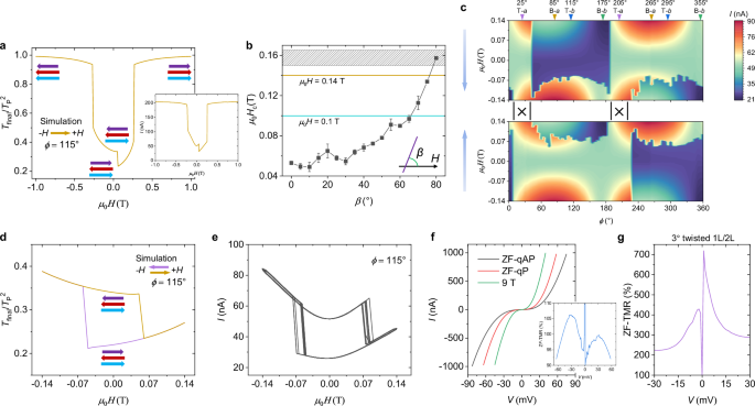
a Simulated conductance, \(G\propto {T}_{{final}}\), when sweeping field from −1 T to 1 T along the b-axis of the top monolayer flake. TP is the electron transmissivity for perfectly parallel spin alignment. Inset of the main panel shows the magnetization process, see Supplementary Movie 2 and the description in Supplementary Information. Right inset shows the experimental result extracted from Fig. 1h. b Black dots are the extracted critical field (Hc) from Fig. 1f, at which spin-flip happens in the top CrSBr monolayer. β is the angular deviation to the b-axis (purple line) of the top monolayer, see inset. The filled pattern shows the minimal Hc of the spin-flip in the natural CrSBr bilayer extracted from Fig. 1f and Supplementary Fig. 1b when sweeping field along its b-axis. The gold and cyan lines denote two representative field sweep amplitudes in our experiments. The error bar and width of the filled pattern denote the range of the extracted Hc owing to hysteresis and thermal fluctuations. c Field orientation dependence of the tunneling current for field oriented within the ab plane. ±0.14 T field sweep range and 20 mV DC bias are used. At the positions marked by “|x|”, no bistable states appear at ZF. d In analogy to (a), but dual sweeping field between ± 0.14 T. e, Experimental results of tunneling current versus sweep field between ±0.14 T for 10 successive loops along the b-axis of the top monolayer flake. f I-V curves at ZF and 9 T. Inset, calculated ZF-TMR ratio as a function of bias based on the ZF I-V curves of ZF-qP versus ZF-qAP. g ZF-TMR ratio of a 3° twisted device.
Robust nonvolatility in twisted 2L/1L MTJ
Interestingly, for several Φ, we observe two tunneling current states at ZF (i.e., ZF NV) consistent with the schematic in Fig. 1b, but this NV does not appear stably (Supplementary Fig. 3). Furthermore, for most Φ in Fig. 1f, only one tunneling current is observed at ZF. The reason is that such major loops54 of ±2 T sweep field range flip not only the magnetization of the top monolayer between → and ← but also the magnetization of the bottom bilayer between ⇄ and ⇆ instead of a pinned configuration as indicated by Fig. 1b and see Supplementary Movies 1 and 2 and descriptions in Supplementary Information. If a spin configuration is fixed in the bottom CrSBr bilayer at ZF, the experimentally observed ZF NV can be reproduced by the micromagnetic simulations (Supplementary Figs. 3 and 4).
The above results strongly suggest that we need to reduce the amplitude of the field sweep (i.e., minor loop)54 to better pin the spin configuration in the bilayer. From Fig. 1f and Supplementary Fig. 1b, we find that the smallest Hc to flip the spins in the natural CrSBr bilayer is ~0.15 T when the field is along the b-axis (the filled pattern in Fig. 2b). We further extract the Hc versus angle relative to the b-axis (β, inset of Fig. 2b) that flip the spin in the CrSBr monolayer from Fig. 1f. It is found that Hc increases with β (Fig. 2b) resulting from the uniaxial in-plane magnetic anisotropy that persists even to the monolayer limit.
Figure 2b shows that for fields less than 0.15 T the spin configuration in the bottom CrSBr bilayer can be well pinned at ZF but that the spin orientations in the top CrSBr monolayer can be switched, which is first confirmed by the simulations in Fig. 2d and Supplementary Fig. 5. Then, more convincingly, the field-direction-dependent transport measurements in Fig. 2c display ZF NV over extensive angular Φ ranges except for the angular ranges marked by “|x|” since the ±0.14 T sweep field range we used is not enough to flip the spin in the CrSBr monolayer near its a-axis (see Fig. 2b). The observed ZF NV is very stable, as checked by 10 hysteresis loops at different Φ (Fig. 2e and Supplementary Fig. 6). Figure 2b also reveals that the range of Φ where the ZF NV appears will shrink when the amplitude of the sweeping field is reduced, which is validated by the experiments in Supplementary Fig. 7. In the previous discussion, we argued that the flipped spin configurations in the bottom bilayer result in volatility at ZF using the major loops, which is further confirmed by the mirrored tunneling current curves55 in Supplementary Fig. 6l-n. Such minor loop results are obtained after a large field stimulation flips the spin configuration to its time-reversal copy in the bottom bilayer. The mirrored results are also reproduced by simulations (Supplementary Fig. 5).
Next, we investigate the performance of the twisted CrSBr 2L/1L MTJ. Figure 2f is the I-V feature of the binary states at ZF, labeled “ZF-qAP” and “ZF-qP” in line with Fig. 1b for the low-conductance state and high-conductance state, respectively. The I-V curve at 9 T is also presented for comparison, whose tunneling current is the largest because the spins in the twisted 3-layered stack are all perfectly parallel at 9 T. The inset of Fig. 2f shows the ZF-TMR ratio between “ZF-qAP” and “ZF-qP”, which reaches up to 100%. A more than 130% ZF-TMR ratio is realized in another 45° twisted 2L/1L MTJ (Supplementary Fig. 9). In a 3° twisted 1L/2L MTJ, the ZF-TMR is even higher, up to 700% (Fig. 2g and Supplementary Fig. 10). Note that the 3° twisted 1L/2L MTJ has the top bilayer and bottom monolayer. The experimental TMR agrees with the conclusion in ref. 37, that is, a smaller θtwist favors a larger TMR. Moreover, analogous behaviors are also reproduced in the 3° twisted 1L/2L MTJ (Supplementary Fig. 10), which strongly indicates that the formed moiré superlattice with a small θtwist (Supplementary Fig. 10a) does not produce a strong interlayer coupling but instead decoupling at the twisted interface in the CrSBr system, as also validated by our density functional theory (DFT) calculations (see Supplementary Table 1 and Methods). More remarkably, the high-temperature measurements demonstrate that the ZF NV is robust close to TN but a single state at ZF once the temperature is above TN (Supplementary Figs. 8 and 11). Thus, nonvolatile 2D MTJs with an asymmetric structure are successfully achieved.
The ZF NV in the twisted CrSBr 2L/1L MTJs is observed over almost all Φ except for the angular ranges marked by “|x|” (Fig. 2c, Supplementary Figs. 7, 9b and 10d). In comparison, the ZF NV only appears in narrow angular Φ ranges in the symmetric structures of twisted CrSBr 2L/2L MTJs and twisted CrSBr 1L/1L MTJs, see ref. 37. This is because, in addition to the in-plane uniaxial magnetic anisotropy which is the only source for pinning in the symmetric twisted structures37, the twisted 2L/1L structure has an additional pinning strength derived from the interlayer AF exchange interactions in the bottom untwisted bilayer relative to the top monolayer.
Four states in twisted 1L/2L/1L MTJ
As shown in Fig. 1c, d, we misaligned the top CrSBr monolayer to form one twisted interface in the twisted 2L/1L MTJs. Next, we further extend this concept by misaligning an additional CrSBr monolayer under the bilayer to form a second twisted interface. In this twisted 4-layered stack (Fig. 3a), 60° twist angles are used, and note the relative misaligned angle is also 60° between the top and the bottom monolayers (top view, upper panel of Fig. 3a). To better exhibit the spin configurations at the three interfaces of the twisted 4-layered stack, we redraw a diagram based on Fig. 1b but shift the arrows only for clarity, as shown in Fig. 3c, in which the spin in the bottom monolayer is denoted by a green arrow. Now, the natural CrSBr bilayer is the mid-flake with an antiparallel spin configuration (the red and blue arrows in Fig. 3c). There are four different spin configurations in the twisted 4-layered stack because of either the qP or the qAP spin arrangement at each of the two twisted interfaces.
Fig. 3: Four states at ZF in a twisted CrSBr monolayer/bilayer/monolayer MTJ.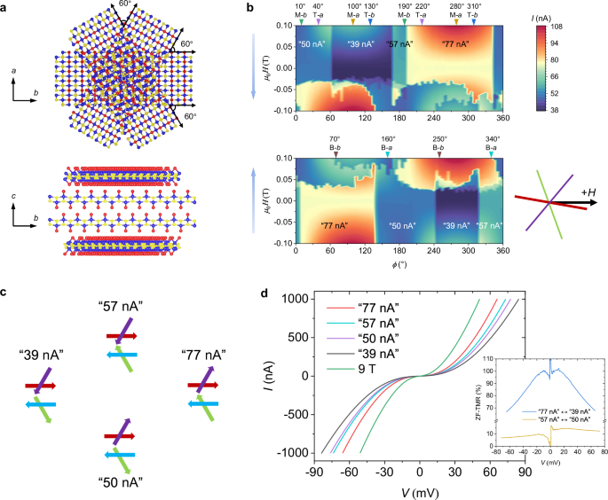
a Schematic of twisted CrSBr monolayer/bilayer/monolayer. Top view in the upper panel and side view in the lower panel. a, b, c crystal axes of the mid bilayer are indicated. b Field orientation dependence of the tunneling current for field oriented within the ab plane. ±0.1 T field sweep range and 20 mV DC bias are used. Two blue arrows indicate the sweeping direction of the field, backward sweeping for the top panel and forward sweeping for the bottom panel. Inverted triangles with angles mark the position of the crystal axes. T-a: the a-axis of the top monolayer flake, M-b: the b-axis of the mid bilayer flake, B-a: the a-axis of the bottom monolayer flake and so on. We label the four nonvolatile states with each ZF current. Inset shows the external field (H) direction relative to the easy axes of the three CrSBr flakes when Φ = 0°. Purple, red and green lines correspond to the easy axes of the top, mid and bottom flakes, respectively. c Four spin configurations correspond to the different tunneling currents at ZF. Purple arrow for the spin in the top monolayer, red and blue arrows for the spins in the mid bilayer, and green arrow for the spin in the bottom monolayer. d Four I-V curves at ZF and one at 9 T. Inset, calculated ZF-TMR ratios as a function of bias based on the ZF I-V curves of “77 nA” versus “39 nA” and “57 nA” versus “50 nA”.
The twisted 2L/1L in Fig. 1d is replaced with the 4-layered stack in Fig. 3a to form a twisted 1L/2L/1L MTJ. Supplementary Fig. 12a shows the field-direction-dependent tunneling currents with the field swept between ±2 T, which have similar characteristics as Fig. 1f except for an additional hump appearing at the right side of the large hump due to the bottom CrSBr monolayer. Again, we do not observe any stable ZF NV if the applied magnetic fields are too large. Figure 3b shows the field-direction-dependent tunneling currents by sweeping the field between ±0.1 T. As distinct from the bistable states in Fig. 2c and Supplementary Figs. 9b and 10d, four states appear at ZF in Fig. 3b. We label the four ZF states with each tunneling current value at ZF (the measurement error is <1 nA). The four ZF states correspond to the four spin configurations in Fig. 3c. If the spins are in qAP (qP) alignment at both twisted interfaces, the tunneling current is the lowest (largest). For the other two cases with qAP alignment at one twisted interface and qP alignment at the other twisted interface, ideally they should display an identical moderate tunneling current, while the asymmetries introduced via device fabrication, such as nonidentical twist angles and strains, cause different tunneling currents in a practical situation (Supplementary Fig. 19). Note that the corresponding relationship between ZF states and spin configurations in Fig. 3c is strictly linked, which will be discussed later. The I-V curves of the four ZF states and the 9 T state are plotted in Fig. 3d. An up to 100% ZF-TMR ratio is obtained in the interchange between the “77 nA”-state and the “39 nA”-state. The interchange between the “57 nA”-state and the “50 nA”-state gives the lowest ZF-TMR ratio but it is still more than 10%, and the additional ZF-TMR ratios for the other cases are given in Supplementary Fig. 12c.
Manipulation among the four states
The inset in Fig. 3b shows the external field direction relative to the easy axes of the three CrSBr flakes in the twisted 4-layered stack when Φ = 0°, and Fig. 3b shows that rotating the orientation of the field sweep determines which two of the four ZF states in the twisted 1L/2L/1L MTJ can be interchanged. For example, the “77 nA” -states can be turned to the “50 nA”-state and the “39 nA”-state by forward sweeping the field and returning to ZF at 10° <Φ < 60° and 60° <Φ < 135°, respectively. We now further investigate the interchange principle. First, we extract four representative operations (see Fig. 4b; H(Φ) means the external field is oriented at Φ) that are closely related to the crystal axes of the three CrSBr flakes in the twisted 1L/2L/1L MTJ by recapping the results of Figs. 3b, 2c and Supplementary Figs. 9b and 10d. The spin configuration in the mid CrSBr bilayer is constantly pinned owing to the ±0.1 T field sweep range. Hence, to switch the four ZF states, one only needs to manipulate the spins in the top and bottom monolayers. See Fig. 4b, H(Φ = 40°) is oriented along the a-axis of the top monolayer, whose spin is pinned owing to the strong uniaxial magnetic anisotropy (see Fig. 2b). However, H(Φ = 40°) corresponds to a 30° deviation to the b-axis of the bottom monolayer (see Fig. 4b), so a ±0.1 T field is enough to flip the spin in the bottom monolayer as indicated by Fig. 2b. It is found in Fig. 3c that solely manipulating the spin in the bottom monolayer can realize two interchanges, that are, “57 nA”-state ↔ “39 nA”-state and “50 nA”-state ↔ “77 nA”-state, which is established by the experimental results (Fig. 4d, f). Based on the same principle, H(Φ = 160°) solely manipulates the spin in the top monolayer to realize the interchanges of “57 nA”-state ↔ “77 nA”-state and “50 nA”-state ↔ “39 nA”-state (Fig. 4c, e). Figure 4a summarizes the interchange relationships among the four ZF states, which suggests that we can set the device to any of the four states and even indirectly achieve the interchanges of the “50 nA”-state ↔ “57 nA”-state and the “39 nA”-state ↔ “77 nA”-state by combining the H(Φ = 160°) and H(Φ = 40°) operations to switch the spins in the top/bottom monolayers subsequently.
Fig. 4: Manipulating the four nonvolatile states in the twisted CrSBr monolayer/bilayer/monolayer MTJ.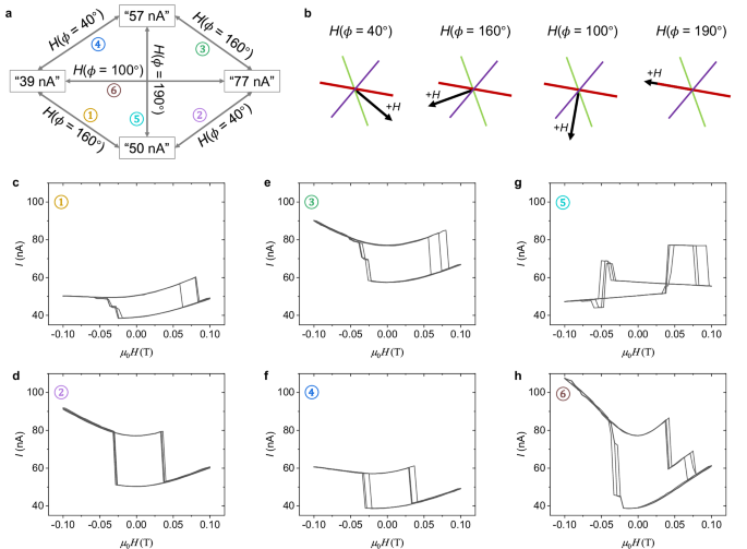
a Diagram of interchange relationships among the four states connected by H(Φ). H(Φ) means the external field is oriented at Φ. There are six interchanges, which are numbered. b Analagous to the inset of Fig. 3b, but with different Φ. c–h Experimental demonstrations of the interchange relationships in (a). Three successive loops are used for each interchange. ±0.1 T field sweep range and 20 mV DC bias are used.
In addition, direct interchanges of “50 nA”-state ↔ “57 nA”-state and “39 nA”-state ↔ “77 nA”-state can be established if an operation can simultaneously switch both the spins in the top/bottom monolayers. Figure 3c shows that the relative angle of the spins in the top/bottom monolayers is always 120° but in opposite orientations for the “50 nA”-state and the “57 nA”-state, i.e., the spins in the top/bottom monolayers of the “50 nA”-state (“57 nA”-state) point to the right (left) of the b-axis of the mid CrSBr bilayer. We further note that the b-axis of the mid bilayer is the angular bisector of this 120° relative angle, see H(Φ = 190°) in Fig. 4b, which corresponds to a 60° deviation from both the b-axes of the top/bottom monolayers. Accordingly, per Fig. 2b, a ±0.1 T field is sufficient to simultaneously operate the two spins in the top/bottom monolayers using H(Φ = 190°) to enable a direct interchange of “50 nA”-state ↔ “57 nA”-state. Based on the same analysis, H(Φ = 100°) enables a direct interchange of “39 nA”-state ↔ “77 nA”-state. Both direct interchanges are experimentally verified (Fig. 4g, h). These interchanges are also shown in Fig. 4a.