
Basic SMALL regulated YES gate
In the basic SMALL YES gate module, the SMALL-mediated DNAzyme cleavage reaction was allosterically activated by introducing trigger D to produce stacking interaction 1 during the end’s proximity between DNA strands D and B (Fig. 2a). The basic module consists of three components: DNAzyme-1 (B/C, a basic receptor), trigger D and substrate A (containing a central ribonucleotide as the cleavage site) (Fig. 2a). Initially, DNAzyme-1 bound to substrate A via a 25 nt binding region to form complex (B/C/A), a metastable DNAzyme cleavage state (Fig. 2a). The length of the binding region between DNA strand B and substrate A was designed as 3 bp to ensure the activity of DNAzyme-1 maintained in the inactive OFF state. Upon introducing trigger D to bind with substrate A, the ends proximity of DNA strands D and B facilitated the generation of stacking interaction 1 (Fig. 2a). Assisted by stacking interaction 1, DNAzyme-1 was allosterically activated to perform the cleavage reaction (Fig. 2b).
Fig. 2: The basic SMALL YES gate.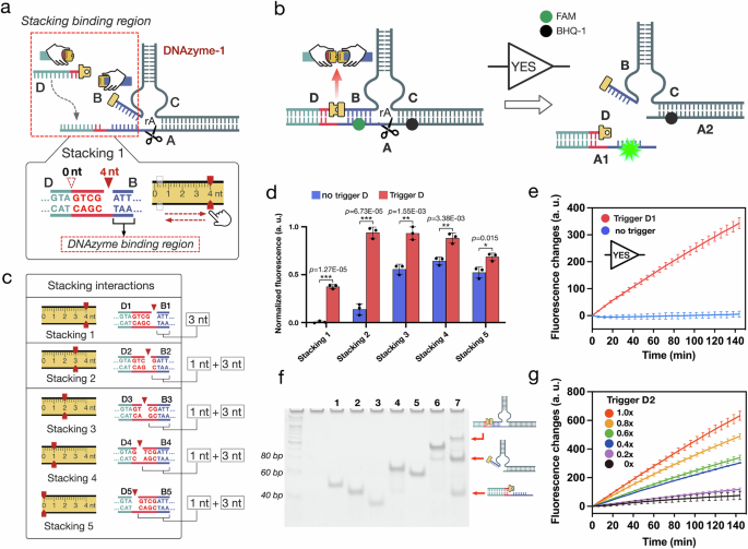
a Illustrations of the basic SMALL YES gate module. b The design details of the basic SMALL YES gate regulation module. c Schematic illustration of the stacking interactions adjusting in the module. d Histogram of the fluorescence results of the SMALL regulations with different stacking interactions (140 min, mean ± SD, n = 3 from independent experiments, *p ≦ 0.05, **p ≦ 0.01, ***p ≦ 0.001). e Fluorescence results of the basic SMALL YES gate with the regulation of stacking interaction 1. complex (A/B1/C) = 0.2 μM and D1 = 0.2 μM. a.u.: arbitrary units (mean ± SD, n = 3 from independent experiments). f Native PAGE analysis of the basic SMALL YES module. Lane 1, A; lane 2, C; lane 3, B2; lane 4, complex (A/C); lane 5, DNAzyme-1 (B2/C); lane 6, complex (A/B2/C); lane 7, complex (A/B2/C) + D2. All DNA strands were used at 800 nM in reactions conducted at 25 °C. The PAGE experiment was independently repeated three times, yielding similar results. g Fluorescence results using different input D2 concentrations of 0×, 0.2×, 0.4×, 0.6×, 0.8× and 1.0×, with 1× as 200 nM (mean ± SD, n = 3 from independent experiments). Source data are provided as a Source Data file.
In the YES gate configuration, DNAzyme-1 was initially designed to be inactive but could reach the activation threshold with assistance of the stacking interaction. The activity state of DNAzyme-1 was modulated by programming the stacking interactions at its left side (Fig. 2c, stacking interactions). We implemented five different stacking regulation variants, utilizing modifications of DNA strands B and D (Fig. 2c, B1 to B5 and D1 to D5). The efficacy of the YES gate was evaluated using a fluorescence assay, where the activation of DNAzyme cleavage by stacking interactions resulted in a notable increase in fluorescence intensity, due to the separation of the fluorophore FAM from the quencher BHQ-1 (Fig. 2b). These results indicate that the optimal signal-to-noise ratio of the YES gate was obtained when using DNA strands B1 and D1 (stacking interaction 1) (Fig. 2d). The relevant regulatory mechanism analysis, structural simulations and dynamic fluorescence results can be found in Supplementary Figs. 2–11 and 22–25.
In the optimal YES gate experiments (Fig. 2e), the fluorescence intensity gradually increased upon introducing trigger D1, indicating that the stacking interaction indeed allosterically activated DNAzyme-1. In contrast, no significant fluorescence increase was generated without trigger D1 (Fig. 2e). The YES gate reaction triggered by stacking interaction 2 was verified by native polyacrylamide gel electrophoresis (PAGE). When introducing trigger D2, the disassembly of DNAzyme-1/substrate A was clearly observed for the stacking interaction-triggered DNAzyme-1 (Fig. 2f, lane 7). Moreover, the YES gate was also tested by the experiments with varying trigger concentrations, where the fluorescence intensity gradually increased as the concentrations of trigger D2 increased from 0 to 200 nM (Fig. 2g). The simulation results can be found in Supplementary Figs. 52–55.
Dual-input SMALL logic function switching
Dual-input SMALL logic function switching was performed by programming two stacking interactions on one DNAzyme to allosterically control the cleavage (Fig. 3a, d). Taking advantage of the flexible DNAzyme construct, we implemented down and up SMALL logic function switching by programming stacking interactions at different structural sites (Fig. 3a, d). In the down SMALL regulation, two logic gates with the functions of AND and OR were constructed by using DNAzyme-2 and DNAzyme-3, respectively. (Fig. 3a).
Fig. 3: The dual-input SMALL logic function switching.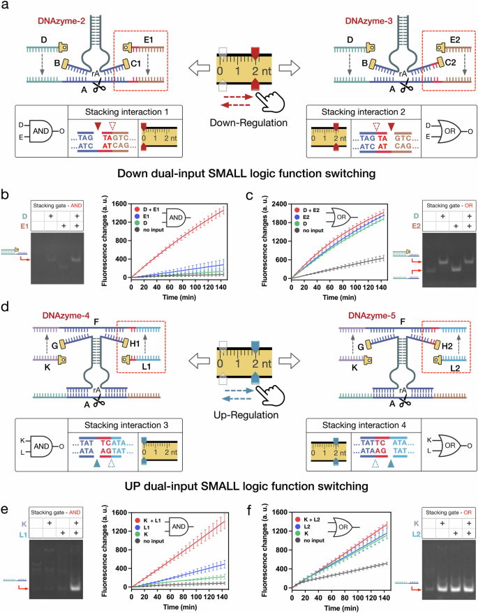
a Schematic illustration of the downregulation SMALL module, in which the logic function can be switched by adjusting the stacking interactions on the right side of DNAzyme-2 and -3. DNAzyme 2 with stacking interaction 1 perform AND logic, while DNAzyme-3 with stacking interaction 2 perform OR logic. b, c Fluorescence and PAGE results of the AND and the OR gates in the downregulation SMALL module (mean ± SD, n = 3 from independent experiments). In the PAGE results, All DNA strands were used at 200 nM in reactions conducted at 25 °C. d–f Illustrations, designs and results of the upregulation SMALL module regulated by stacking interactions 3 and 4 (mean ± SD, n = 3 from independent experiments). In the PAGE results, All DNA strands were used at 200 nM, except for DNA substrate A, which was used at 800 nM, in reactions conducted at 25 °C. Source data are provided as a Source Data file.
In the down regulation, the SMALL AND gate was constructed by using DNAzyme-2 (B/C1) to respond to two stacking input D and E1 (Fig. 3a). In the experiments, DNAzyme-2 bound to substrate A to form complex (B/C1/A), a metastable DNAzyme cleavage state (Fig. 3a). Initially, DNAzyme-2 was in the OFF state when stacking interaction 1 was set as site 0 nt at the right side of DNAzyme-2. Introducing either stacking input D or E1 cannot give any significant fluorescent signal, indicating that DNAzyme-2 can not be activated either by a single stacking interaction (Fig. 3b). Only when both stacking inputs were introduced simultaneously, was the fluorescence intensity observed to increase significantly (Fig. 3b). These experimental results demonstrated that DNAzyme-2 can be allosterically activated by both two stacking interactions to cleavage the substrate. The result of the AND gate was also verified by native PAGE (Fig. 3b).
Based on SMALL method, the DNA logic gate function was designed to switch from AND to OR by simply adjusting the stacking interaction from site 0 nt to 2 nt, with only a 2 nt molecular architecture change between DNAzyme-2 and DNAzyme-3 (Fig. 3a). In the results, introducing either stacking input D or E2 can produced a significant fluorescence increase, indicating that just one stacking interaction was able to allosterically trigger DNAzyme cleavage in the OR gate (Fig. 3c). The OR gate was also verified by native PAGE (Fig. 3c). The experimental results well confirm the SMALL based function switching between AND and OR gates, which simply requiring a 2 nt molecular architecture change of the DNAzyme (Fig. 3a). Similarly, in the up SMALL regulation, the function switching of AND and OR gates were implemented by programming stacking interactions 3 and 4 in DNAzyme-4 and DNAzyme-5, respectively (Fig. 3d). The results of the upregulating AND and OR gates are shown in Figs. 3e and f. More information on related structural design, performance analysis, systematic optimization, and simulations can be found in Supplementary Figs. 12–27 and 56–57.
Multi-input SMALL logic function switching
We further proposed multi-input SMALL logic function switching by cooperatively programming multiple stacking interactions to activate the DNAzyme cleavage (Fig. 4a, b). For the multi-input SMALL logic gates, their logic functions could be switched by precisely setting the combination of the four stacking interactions (Fig. 4a, c). For example, to perform a four-input AND gate, the four stacking interactions was set as combination-1 {2, 0, 1, 1 nt} (Fig. 4a, c). Here, DNAzyme-6 was designed as metastable to ensure that the cleavage was activated, only when all four stacking interactions were introduced simultaneously (Fig. 4b and Supplementary Fig. 28). In the experimental results, a significant increase in fluorescence intensity was only observed when all four stacking inputs present simultaneously (Fig. 4d). It should be noted that no significant fluorescence increase was observed when any of the four stacking interactions were missing (Fig. 4d). Similarly, the native PAGE results also confirmed the well performance of the four-input AND functions, where the cleavage was clearly observed only when all four stacking interactions were present simultaneously (Fig. 4e).
Fig. 4: The multi-input SMALL logic function switching.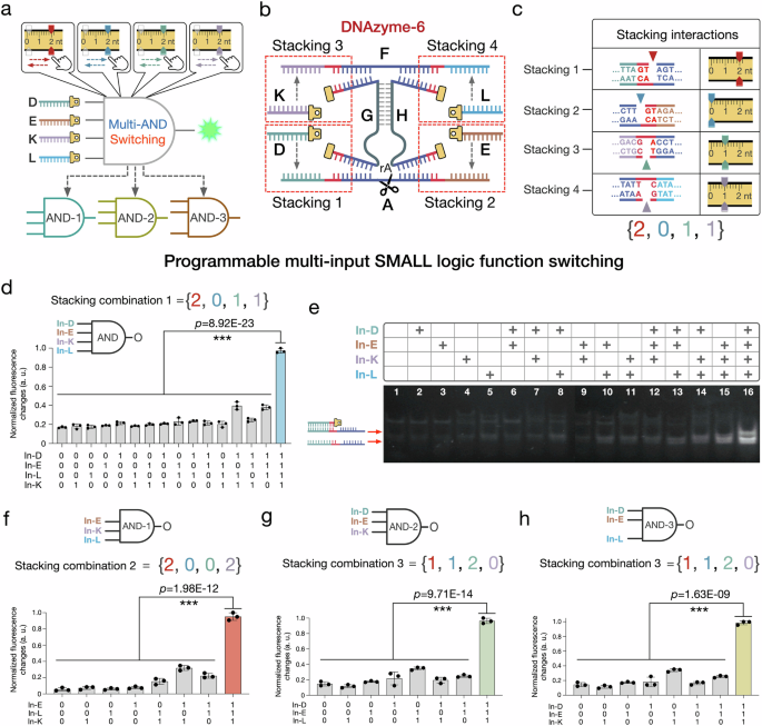
a Illustrations of the multi-input SMALL AND function switching. b The design details of the four-input AND gate module regulated by stacking interactions 1, 2, 3 and 4. c Schematic diagram of the stacking interactions combination of the four-input SMALL AND gate. d, e Fluorescence and PAGE results of the four-input SMALL AND gate triggered by all possible input conditions of the four stacking interactions (15 h, mean ± SD, n = 3 from independent experiments, *p ≦ 0.05, **p ≦ 0.01, ***p ≦ 0.001). In the PAGE results, All DNA strands were used at 200 nM, except for DNA substrate A, which was used at 800 nM, in reactions conducted at 30 °C. f–h The illustrations and histograms of the three-input SMALL AND gate 1 with stacking combination 2, and the three-input SMALL AND gates 2 and 3 with stacking combination 3 (15 h, mean ± SD, n = 3 from independent experiments). Statistical analysis for figures f to h was performed using a two-sided test. Source data are provided as a Source Data file.
Based on the initial four-input SMALL AND gate, the logic functions of the multi-input logic gates were switched by precisely setting the stacking interactions combinations to perform different three-input AND gate-1, -2, and -3 (Fig. 4f–h). For instance, by programming the stacking interactions setting as combination-2 {2, 0, 0, 2 nt}, the logic function was switched to three-input AND gate-1, triggered by stacking inputs (E, K, L) (Fig. 4f). In the experiments of three-input AND gate-1, a significant increase in fluorescence intensity was observed when stacking inputs (E, K, L) were simultaneously introduced to allosterically activate the cleavage. Conversely, no significant increase in fluorescence was detected when any of the three stacking interactions were absent. (Fig. 4f). Similarly, when adjusting as combination-3 {1, 1, 2, 0 nt}, two kinds of the specific three-input stacking AND gates-2 and -3 were performed, triggered by stacking inputs (D, E, K) and (D, E, L) (Fig. 4g, h). In addition, we conducted tests on multiple additional four-input SMALL gates with different stacking interactions combinations. The results demonstrate that the performance of these four-input SMALL gates can also be diversely modulated by setting the stacking interactions combinations (Supplementary Figs. 29–37).
Cascaded SMALL network logic function switching
To investigate whether the SMALL based function switching can be cooperatively integrated in cascaded DNA logic networks, the allosteric stacking interactions are programmed in a hierarchical manner. We firstly constructed a three-level cascaded SMALL network (consisting of the three modules as Level-1, -2 and -3, Fig. 5a) to perform logic computing functions (Fig. 5b). In the Level-1 module, DNAzyme-7 was allosterically triggered by introducing DNA strand X to produce stacking interaction 1 (Fig. 5a). Assisted by the stacking interaction, DNAzyme-7 was activated to cut the target DNA substrate (U/T) at a ribonucleotide modification in the middle of DNA strand U. Then, DNA complex (U*/T) was released and served as the trigger for the next Level-2 module (Fig. 5a). In the whole cascaded process, the stacking interaction signal was hierarchically transmitted from Level-1 to Level-3 modules, thus triggering the activity of DNAzyme-9 and producing a fluorescent increase (Fig. 5a).
Fig. 5: The cascaded SMALL network function switching.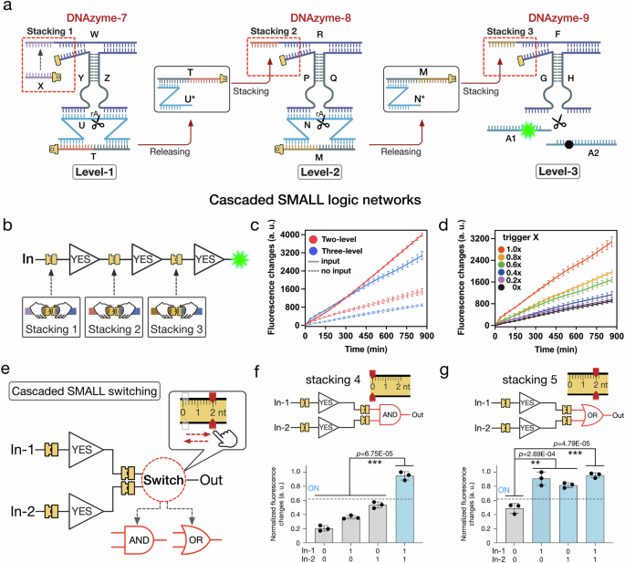
a The design details of the three-level cascaded SMALL network. b Illustrations of the cascaded SMALL logic network. c Fluorescence results of the two-level network triggered by DNA strand T and the three-level network triggered by DNA strand X (mean ± SD, n = 3 from independent experiments). d Fluorescence results of the three-level SMALL network triggered by using gradient DNA strand X concentrations, as 0×, 0.2×, 0.4×, 0.6×, 0.8× and 1.0×, with 1× as 200 nM (mean ± SD, n = 3 from independent experiments). e Illustrations of the cascaded SMALL network function switching. f, g Fluorescence results of the YES/YES-AND network with stacking interaction 4 and the YES/YES-OR network with stacking interaction 5 (15 h, mean ± SD, n = 3 from independent experiments). Statistical analysis for figures f and g was performed using a two-sided test (*p ≦ 0.05, **p ≦ 0.01, ***p ≦ 0.001). Source data are provided as a Source Data file.
In the experiments of the three-level cascaded SMALL network, an increase in fluorescence was observed upon introducing DNA strand X (Fig. 5a, c). Additionally, to investigate the activating effects of the initial triggers in the cascaded SMALL networks, we implemented the experiments by varying the concentrations of trigger X (Fig. 5d). The fluorescence intensities were observed to increase gradually with increasing DNA trigger X concentrations (Fig. 5d). Meanwhile, the effects of the cascading level numbers were also considered in the experiments. Here, a two-level cascaded SMALL network was constructed consisting of two modules Level-2 and -3. An attenuation phenomenon of the fluorescence increases was observed in the three-level network when compared with the two-level networks, possibly due to the increased complexity in system and the incomplete substrate cleavage by the stacking triggered DNAzyme in each layer (Fig. 5c and Supplementary Fig. 51). These data indicated that the cascaded stacking interaction signal transmission was indeed initiated from the upstream to the downstream (more experimental details and results can be found in Supplementary Figs. 38–49 and 58–59).
To demonstrate the possibility to perform function switching in the cascaded SMALL networks, we constructed tree topology cascaded SMALL networks to perform YES/YES-AND and YES/YES-OR logic circuits, respectively (Fig. 5e). The logic function switching was implemented by programming the stacking interaction in the downstream gate with only 2 nt molecular architecture change (Fig. 5e). Specifically, the cascaded network performed YES/YES-AND function when stacking interaction 4 was set as site 0 nt, while the function of cascaded network was switched to YES/YES-OR with stacking interaction 5 set as site 2 nt (Fig. 5e). The corresponding fluorescent results demonstrated the performances of the logic function switching in the cascaded SMALL networks (Fig. 5f, g). It should be noted that during the operations of the cascaded SMALL circuits, a certain degree of signal attenuation and fidelity degradation occurs. We attribute this phenomenon to accumulative signal attenuation during top-down signal transmission, resulting from the incomplete cleavage of substrate DNA strands by DNAzyme. Detailed structural and procedural analyses can be found in Supplementary Fig. 50.
SMALL based logic function switching for endogenous microRNA sensing
The SMALL based function switching was further implemented in real cellular environments, triggered by endogenous microRNAs, which are abundantly expressed in various tumor cells and play significant roles in clinical tumor diagnosis and therapeutics39,40. We selected microRNAs 21, 17 and 30a as the target input signals for the SMALL-based logic operations. In the dual-input SMALL AND gate, microRNAs 21 and 17 were used as endogenous input signals. Assisted by DNA strands S1 and S2, the two DNA/RNA complexes S1/microRNA 21 and S2/microRNA 17 were able to bind with DNAzyme-10 to form stacking interactions 1 and 2 (Fig. 6a). Then, the activated DNAzyme-10 cleaved substrate A, generating a measurable FAM green fluorescence signal (Fig. 6a). Similarly, the functionality of the SMALL logic gate was modulated by programming the stacking interactions of DNAzyme-10. By setting stacking interactions 1 and 2 as {2, 0 nt} and {1, 1 nt}, respectively, the microRNA logic gates were successfully switched to operate as AND and OR gates. (Fig. 6b and Supplementary Figs. 65–66).
Fig. 6: SMALL-based microRNA logic function switching in living cells.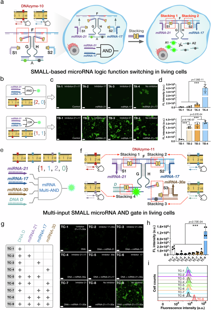
a Schematic representation of the SMALL microRNA logic gate for endogenous microRNA imaging. b Schematic diagram of the SMALL microRNA gates with different stacking interactions combinations. c Confocal laser scanning microscopy (CLSM) imaging results of FAM green fluorescence in the MCF-7 cells after treatment with the AND and OR SMALL microRNA gates. The selective microRNA control groups were implemented by pretreating specific inhibitors for microRNAs 21 and 17. d FAM green fluorescence intensity statistics of the MCF-7 cells after treatment with the dual-input AND and OR gates, as shown in Figure (c) with 20 um scale bars (48 h, mean ± SD, n = 4 from biologically independent experiments). e, f Schematic illustration and the design details of the multi-input SMALL microRNA AND gate regulated by four stacking interactions 1, 2, 3 and 4. g CLSM imaging results of FAM green fluorescence in the HeLa cells after treatment with the four-input SMALL microRNA AND gate. h FAM green fluorescence intensity statistics of the HeLa cells after treatment with the four-input AND gate, as shown in Figure (g) with 20 um scale bars (48 h, mean ± SD, n = 4 from biologically independent experiments). i Flow cytometry analysis of FAM green fluorescence in the HeLa cells treated with the four-input AND gate in different microRNA control groups. The data were analyzed using GraphPad Prism 8.0 and SPSS 17.0. All error bars indicate the standard deviation (SD) of the mean. One-way ANOVA was applied for multiple comparisons, and the two-sided test was used for comparison between two groups: *P < 0.05; **P < 0.01; and ***P < 0.001. Source data are provided as a Source Data file.
The SMALL based logic function switching was first tested in the breast cancer cell line (MCF-7) to confirm their capability in living cells. Initially, specific chemical RNA inhibitors for microRNAs 21 and 17 were used to selectively control the microRNA activity. The SMALL logic gates were then introduced into the cells using Lipofectamine 3000 (Fig. 6a, b). After that, cellular computing results were analyzed using confocal laser scanning microscopy (CLSM) (Fig. 6c, d). In the AND gate configuration with the stacking combination of {2, 0 nt}, a significant fluorescent signal was only observed when both microRNAs 21 and 17 were present, and inhibition of any one microRNA resulted in negligible fluorescence (Fig. 6c). These findings were corroborated by flow cytometry results (Supplementary Fig. 65). Additionally, the OR gate was effectively switched using the stacking combination of {1, 1 nt} to respond to microRNAs 21 and 17 (Fig. 6b-d and Supplementary Fig. 66), demonstrating the simple and flexible function switching of the SMALL platform in living cells.
To further extend the versatility of the SMALL based logic operations, a four-input AND gate was constructed, triggered by endogenous microRNAs (microRNA 21, 17, and 30a) and an exogenous DNA input (DNA strand D) (Fig. 6e, f). Assisted by DNA strands S1, S2, S3 and D, the three DNA/RNA complexes (S1/microRNA 21, S2/microRNA 17 and S3/microRNA 30a) and DNA D engaged with DNAzyme-11, forming stacking interactions 1, 2, 3 and 4, respectively. This activation led to substrate cleavage and the production of a fluorescent signal (Fig. 6e, f). Implemented in a cervical cancer cell line (HeLa), the four-input SMALL AND gate exhibited substantial fluorescence only when all inputs were concurrently present (Fig. 6g, h). In the presence of DNA strand D, introduction of inhibitors for any of the microRNAs significantly reduced fluorescence, confirming the gate’s specificity and sensitivity (Fig. 6g, h). These multi-input logic operations were further validated by additional flow cytometry experiments (Fig. 6i). Details regarding the structural design, performance testing, and anti-interference analysis of the aforementioned miRNA-sensing logic gates are provided in Supplementary Figs. 60–71.
SMALL based logic function switching for gene regulations
Subsequently, a SMALL-based logic function switching system was developed to enable precise gene regulation in cellular environments. To achieve this, we employed antisense oligonucleotides (ASOs) in our system, which are short nucleic acid sequences capable of suppressing gene expression and are commonly utilized in molecular therapeutics for gene regulation41,42. Specifically, ASOs targeting the GFP protein were integrated into our experiments to be regulated via SMALL-mediated cleavage. This integration established the SMALL-ASO logic networks, which controlled DNAzyme activity and thereby indirectly modulated GFP expression levels (Fig. 7a). In the basic YES logic operation, a one-level SMALL-ASO stacking network was established with the stacking interactions combination set to {2, 2 nt} (Fig. 7a). This network employs endogenous microRNA 21 as an input, which forms the DNA/RNA complex S1/microRNA 21 through hybridization with DNA strand S1. This complex subsequently bound to DNAzyme-12 to establish stacking interaction 1 (Fig. 7a). Then, the stacking activated DNAzyme-12 cleaves the DNA protector A*, releasing D-GFP and thus inhibiting GFP protein expression (Fig. 7a). We initially validated the functionality of the YES gate through in vitro experiments (Supplementary Figs. 72 and 73). Subsequently, by setting the stacking interactions combinations to {2, 0 nt} and {1, 1 nt}, we successfully constructed the AND and OR gates, respectively (Supplementary Figs. 74–76). The functionality of these logic gates was evaluated through both in vitro and cellular experiments, demonstrating their capability to efficiently regulate GFP expression levels.
Fig. 7: SMALL-ASO logic network function switching to perform programmable gene regulation in living cells.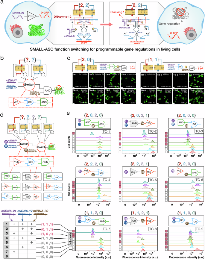
a Schematic illustration of the basic SMALL-ASO YES gate for GFP gene regulation. b Model of the SMALL-ASO cascaded circuit that can switch logic function by adjusting the stacking interactions combination in the upstream gate. MicroRNAs 21 and 17 function as the inputs for activating the upstream gate, while microRNA 30a serves as the input for the downstream gate. c CLSM imaging results of GFP brightness in the MCF-7 GFP cells was used to analyze the AND-AND and OR-AND SMALL-ASO cascaded networks with stacking interactions combinations {2, 0} and {1, 1}, respectively (Scale bars, 20 um). The experiments were independently repeated three times, yielding similar results. d Schematic illustration of the two-level cascaded SMALL-ASO network, in which the logic function can be programmed by adjusting the stacking interactions combinations. e Flow cytometry analysis of GFP brightness in the HeLa GFP cells treated with the cascaded SMALL-ASO networks with nine different logic functions. The data were analyzed using GraphPad Prism 8.0 and SPSS 17.0. Source data are provided as a Source Data file.
Following this, two-level cascaded SMALL-ASO stacking networks were developed to implement logic function switching, enabling more complex regulations of GFP expression. Initially, the function switching mechanism was exclusively established in the upstream gate, which is regulated by microRNAs 21 and 17. Concurrently, the downstream gate was activated by microRNA 30a through an AND logic operation. (Fig. 7b). Initially, the SMALL mechanism was integrated into the upstream gate with two distinct stacking combinations (Fig. 7b). This configuration allows for three types of SMALL-ASO logic operations: YES-AND, OR-AND, and AND-AND, set by the respective stacking combinations of up- {2, 2 nt}, up- {1, 1 nt}, and up- {2, 0 nt}. Similarly, before the operation of the cascaded SMALL-ASO stacking networks, specific chemical RNA inhibitors (targeting microRNAs 21, 17, and 30a) were employed to selectively modulate the activity of these microRNAs. The experimental results confirm that these function switching was effectively implemented in HeLa cells, with molecular architecture change ratios of 0.3% (Fig. 7c). For instance, switching the logic functions from AND-AND to OR-AND involved a mere 2 nt molecular architecture change, accounting for a 0.3% change within the whole 543 nt SMALL-ASO network structure (Fig. 7b, c). Moreover, these results demonstrate the sensitivity and precision of the SMALL-based cellular function switching. Even under identical endogenous conditions of microRNAs 17 and 30a, significantly different computational outputs were achieved (Fig. 7c, TA-2 and TB-2). Additional experimental findings are detailed in Fig. 7c and Supplementary Fig. 79.
The functionality of the SMALL-ASO networks was additionally regulated across both upstream and downstream gates to achieve dual-logic function switching for coordinated gene regulations (Fig. 7d). The SMALL mechanism was implemented both in up- and downstream gates by setting four distinct stacking combinations to implement the function switching (Fig. 7d). This coordinated regulation allowed for the execution of 9 distinct logic functions, managing GFP gene expression in response to 8 unique cellular microRNA conditions (Fig. 7d, e). In total, 72 different SMALL-based gene regulation patterns were achieved in HeLa cells, with molecular architecture change ratios ranging from 0.2% to 0.7% (Fig. 7e). For example, cooperative dual-logic function switching in both upstream and downstream gates facilitated the switch from the AND-AND to the OR-OR configuration. By adjusting the stacking combinations from {2, 0, 2, 0 nt} to {1, 1, 0, 0 nt}, which involved a molecular architecture change ratio of 0.7%, distinct computational outputs were observed, differentiating the AND-AND from the OR-OR SMALL-ASO network (Fig. 7e, TC-1 and TC-9). Relevant cellular experiment data analysis, network structure design, and in vitro performance testing are provided in Supplementary Figs. 77–82.