
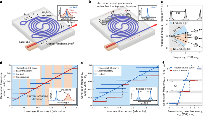
Principle of endless SIL
The concept of endless SIL is shown in Fig. 1, where the feedback-phase dispersion is controlled by design through the placements of the resonator ports within the microresonator (Fig. 1b). The resulting laser trajectory (Fig. 1e) exhibits only transitions between locked states, in contrast to a conventional SIL resonator design (Fig. 1a), which falls out of lock when tuning between the locked states (Fig. 1d). This is enabled by the resonator port placement design, which governs the feedback-phase dispersion of the backreflected light (Fig. 1c,f). Crucially, the port placements need not be controlled on an optical-wavelength scale, as the feedback-phase dispersion varies on a much larger wavelength scale determined by the resonator’s free spectral range (FSR)—approximately 30 cm for a typical 1-GHz FSR.
For modelling this phenomenon, we consider the self-injection-locked laser architecture depicted in Fig. 2a in which a semiconductor laser diode is coupled to a photonic integrated circuit (PIC) microresonator. The resonator includes a drop port with a Sagnac mirror to enable the robust excitation of the counterpropagating resonator mode, which provides broadband deterministic control of the reflection into the laser diode29. This optical feedback modifies the self-injection-locked laser generation frequency ω, so that it generally differs from both free-running laser frequency ωLD and resonator resonance frequency ωC. In the case of multiple microresonator resonances, assuming single-mode operation and negligible nonlinear interactions between the resonator modes, the stationary relation between the generation frequency and free-running laser frequency is given by26
$$\omega -{\omega }_{{\rm{LD}}}={\kappa }_{{\rm{LD}}}\sum _{\mu }{\rm{Im}}[\varGamma (\omega -{\omega }_{{\rm{C}},\mu }){e}^{-i\arctan (\alpha )}]$$
(1)
where κLD is the coupling coefficient between the laser cavity and the PIC, Γ is the optical feedback, α is the linewidth enhancement factor and ωC,μ denotes the μth microresonator resonance (Methods).
Fig. 2: Effect of feedback-phase dispersion ΔΨ on SIL dynamics.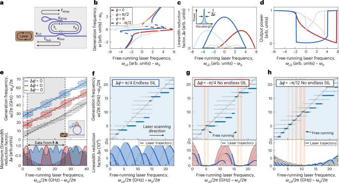
a, Illustration of the relevant time delays τ and coupling factors κ of a self-injection-locked laser. b, Stationary states of a self-injection-locked laser system for different feedback phases. The dashed regions correspond to unstable states. c, Linewidth reduction factors \(\Delta \nu ={(\partial {\omega }_{{\rm{LD}}}/\partial \omega )}^{2}\) corresponding to the stable stationary states shown in b. d, Output power traces of a self-injection-locked laser when sweeping the free-running laser frequency, assuming that mode hops only occur at saddle-node bifurcations (Supplementary Section II). e, Multi-resonance tuning curves (Fig. 1f) for different values of the feedback-phase dispersion ΔΨ (vertically offset for illustrative purposes) and the corresponding maximum linewidth reduction factors of the overlapping SIL states. f–h, Numerical simulations of SIL dynamics for different values of ΔΨ, with all other parameters kept identical, confirm the advantage of a positive ΔΨ in achieving endless SIL with a narrow average linewidth. In these simulations, the free-running frequency is swept from low to high values, but the results generalize to the opposite direction when thermal effects are negligible.
Figure 2b,c shows the tuning curves from equation (1) over a single resonance for different feedback phases, together with the corresponding linewidth reduction factors \(\Delta \nu ={(\partial {\omega }_{{\rm{LD}}}/\partial \omega )}^{2}\), which relate the self-injection-locked laser linewidth to the free-running laser linewidth as δνlocked = δνfree/Δν (often also described by the stabilization coefficient29). In particular, the phase of the backreflected light not only determines the shape of the stationary locking plateau but, more importantly, influences the respective laser linewidths and, hence, the mode-selection dynamics between different branches of the tuning curve, as well as adjacent resonances32 (Supplementary Section II).
In the assumption of negligible interaction between neighbouring resonator modes, the locking dynamics to each resonance is mainly governed by the feedback phase Ψ (Methods). As a result, the central parameter defining the multi-locking-regime landscape is the difference in the feedback phase of the reflected light from one resonance to the next ΔΨ (Fig. 1c,f). By using its 2π periodicity to express ΔΨ as a function of the intra-resonator delays to the right and left sides of the bus coupler (τR and τL, respectively; Methods and Fig. 2a), it is evident that the feedback-phase dispersion can be robustly controlled by the relative placement of the bus and drop couplers along the resonator:
$$\frac{\Delta \varPsi }{2\uppi }\approx {\nu }_{{\rm{FSR}}}({\tau }_{{\rm{bus}}}+{\tau }_{{\rm{drop}}})+\frac{{\tau }_{{\rm{R}}}-{\tau }_{{\rm{L}}}}{{\tau }_{{\rm{R}}}+{\tau }_{{\rm{L}}}}.$$
(2)
where νFSR is the FSR of the microresonator.
This is experimentally demonstrated in Fig. 3a–f, which compares the laser light–current (LI) curves under SIL to three different device architectures. For the device without a drop port (Fig. 3a), the random phase of the Rayleigh-backscattered light leads to random fluctuations in ΔΨ, which is evident from the irregular evolution of the resonance shapes when scanning the injection current. For the resonators coupled to a mirror-terminated drop port (Fig. 3b,c), conversely, the phase evolution is stabilized, implying a constant ΔΨ. Furthermore, a comparison of Fig. 3e,f shows that the value of ΔΨ is dictated by the port positions and waveguide lengths, as described by equation (2). The resonators in Fig. 3b,c have FSRs of 1.44 GHz and 1.5 GHz, respectively, such that with neff = 1.56, the feedback-phase dispersion given by equation (2) is ΔΨ = 0.16π and ΔΨ = −0.57π, respectively, agreeing closely with the experiments shown in Fig. 3e,f. This also demonstrates that to control the feedback-phase dispersion to guarantee endless SIL (Fig. 1c), the backreflector port placement does not need to be controlled at the wavelength scale: the difference in port placement along the spiral cavity between the devices in Fig. 3b,c is of a few centimeters.
Fig. 3: Experimental demonstration of feedback-phase-dispersion control and endless SIL.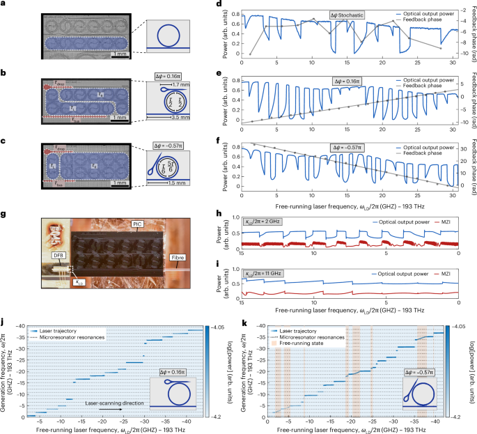
a–c, Microscopy images of spiral microresonators with different architectures: without a drop port (wafer ID: D204 F6 C2 WG3; a), with a symmetric drop port and an extended bus waveguide (wafer ID: D204 F6 C23; b), and with an asymmetric drop port (wafer ID: D204 F6 C28; c). The ΔΨ values have been calculated with physical resonator parameters using equation (2), and originate from the drop-port placement and the lengths of the bus and drop waveguides. d–f, Corresponding experimental LI curves and feedback phases inferred from the resonance shapes, confirming the randomness of Rayleigh backscattering, and demonstrating that a mirror-terminated drop port with a definite position along the resonator can be used to control the feedback-phase dispersion. The DFB–PIC coupling is intentionally reduced to avoid the overlap of locking regimes. g, Photograph of the device in b, showing the hybrid integration of a DFB laser diode and the PIC, with light out-coupled from the bus waveguide to a lensed fibre. h,i, LI curves of the SIL laser and the corresponding MZI traces for two different values of DFB–PIC coupling (κLD), achieved by adjusting the separation between the DFB and PIC facet. j, Spectrogram showing the generation frequency evolution as the free-running laser frequency is scanned through more than two full feedback-phase periods, demonstrating endless SIL (device same as in b and g). k, Spectrogram obtained for the device in c, displaying sections in which the laser falls into a free-running state due to the negative-feedback-phase dispersion.
Next, we show that ΔΨ can be exploited to establish endless SIL. The key mechanism is the oscillatory evolution of the asymmetric locking regimes, controlled by ΔΨ, when tuning the frequency (Fig. 2e). Since laser mode selection is biased towards narrow-linewidth states32,33 (Supplementary Section II), endless SIL is promoted by ensuring that narrow-linewidth (that is, high-Δν) stationary states cover all possible free-running laser frequencies. This is illustrated in Fig. 2e, which shows the tuning curves for different ΔΨ values. For ΔΨ > 0, the periodic oscillation of the locking-regime envelope causes the low-Δν locking regimes to overlap with high-Δν locking regimes, thereby enabling locking to narrow-linewidth states across all free-running laser frequencies. Conversely, for ΔΨ < 0 or ΔΨ ≈ 0, the high-Δν locking regimes bunch together. This leaves regions of ωLD in which only low-Δν states are available, which increases the likelihood of the laser unlocking into a free-running state. Numerical simulations (Supplementary Section I) shown in Fig. 2f–h demonstrate that ΔΨ = −π/4 and ΔΨ = −π/12 can lead to unlocking of the laser when scanning ωLD through such a low-Δν region, whereas for ΔΨ = π/4, the laser is able to select a high-Δν mode at any ωLD, staying endlessly locked. Further numerical simulations (Fig. 4h and Supplementary Section III) show that for the devices presented in this work (Fig. 3a–c), endless SIL is observed when 0.15π < ΔΨ < 1.35π (or equivalently, ΔΨ > 0.15π and ΔΨ < −0.65π, since ΔΨ is 2π-periodic). This confirms that positive values of ΔΨ enable endless SIL, whereas close-to-zero and small negative values lead to unlocking. Importantly, no active feedback-phase control is needed: the collective feedback-phase delay common to all resonances—set, for example, by the phase delay between the laser diode and PIC—merely shifts the periodic mode landscape along the ω = ωLD line, whereas ΔΨ remains fixed, set by the resonator layout, which is determined by the bus and drop waveguide lengths as well as the asymmetry between the bus and drop coupler positions.
Fig. 4: Experimental demonstration of endless SIL and fast frequency tuning.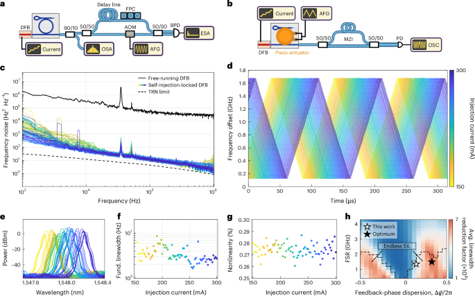
a, Delayed self-heterodyne setup used for the frequency noise measurements. b, Setup used for the linear frequency-tuning experiments. c, Frequency noise measurements as the injection current is scanned from 154 to 300 mA, taken at 2-mA increments without active control of the DFB driving current or feedback phase. The estimated TRN limit of the silicon nitride microresonator is also displayed for comparison. d, Triangular frequency-tuning traces enabled by modulating the microresonator resonances with a monolithic piezoelectric actuator, taken at 2-mA increments as the injection current is scanned from 150 to 300 mA. Consecutive measurements are horizontally offset by 1 μs for illustrative purposes. e,f, Corresponding calibrated spectra (e) and intrinsic linewidths (f). g, Corresponding mean square deviations from a perfect sawtooth waveform, demonstrating state-of-the-art linearity at all injection currents36. The injection current corresponding to each measurement reported in c–g is colour coded, as indicated by the colour bar in d. h, Numerically simulated optimal device design for endless SIL, obtained by maximizing the average linewidth reduction factor. OSA, optical spectrum analyser; AOM, acousto-optic modulator; FPC, fibre polarization controller; AFG, arbitrary waveform generator; BPD, balanced photodetector; ESA, electrical spectrum analyser; OSC, oscilloscope.
Experimental demonstration of endless SIL
We demonstrate endless SIL by butt-coupling an off-the-shelf distributed feedback laser diode (DFB) emitting at 1,548 nm to a PIC containing a spiral microresonator fabricated on silica-cladded Si3N4 (Fig. 3g). We use the resonator architecture shown in Fig. 3b in the following experiments due to its positive-feedback-phase dispersion of ΔΨ = 0.16π, defined as the change in feedback phase over one FSR. The intrinsic loss and coupling rates of the spiral resonator are κ0/2π = 17.1 MHz, κbus/2π = 17.6 MHz and κdrop/2π = 18.2 MHz, corresponding to an intrinsic quality factor of Q0 = 11.3 million. The SIL range measured at the most preferential feedback phase of Ψ = −π/2 is 6.7 GHz, which yields κLD/2π = 11.2 GHz (Supplementary Section V).
As an initial experiment, we modulate the free-running frequency of the DFB by 15 GHz by linearly changing the injection current as the optical output power is monitored with a photodetector. First, we intentionally reduce the coupling rate to κLD/2π = 2 GHz by increasing the distance between the DFB and PIC facet. The measured LI curve (Fig. 3h) shows a sequence of characteristic SIL resonance shapes that gradually change in shape due to the non-zero feedback-phase dispersion (Fig. 3e). These resonances are separated by short sections of higher output power, indicating that the DFB unlocks into a free-running state between resonances as a consequence of the low κLD. The frequency stability is probed using an imbalanced Mach–Zehnder interferometer (MZI), with this MZI trace showing high-frequency oscillation corresponding to free-running states as a result of the linear frequency sweep and no oscillation corresponding to the locked states in which the frequency is stabilized. Second, we increase the coupling rate to κLD/2π = 11.2 GHz. The measured LI curve (Fig. 3i) exhibits direct transitions from one locked state to another without falling into a free-running state in between. This is also validated by the MZI trace, which shows no high-frequency oscillations as observed in the free-running regions shown in Fig. 3h.
To verify endless SIL, we beat the output light with a stable reference laser as the injection current is tuned to obtain the spectrogram (Fig. 3j). Here the laser current is scanned over more than two full periods of feedback-phase oscillations without ever falling into a free-running state. This implies that the laser is self-injection locked across resonances with virtually all possible feedback phases without the need of active control, a feature that we denote as endless SIL. Furthermore, the laser is observed to periodically jump over multiple microresonator resonances, which matches the simulated spectrogram shown in Fig. 2f and indicates that at any injection current, the laser jumps over low-Δν modes by selecting only states that result in an optimal linewidth (Supplementary Section II). Additionally, we repeat the experiment using the resonator architecture shown in Fig. 3c, which has otherwise closely matching design parameters to those shown in Fig. 3b, except it features a negative-feedback-phase dispersion instead. The resulting spectrogram shown in Fig. 3k exhibits regions in which the laser falls into a free-running state, confirming the effect of feedback-phase dispersion on endless SIL.
To showcase endless SIL over a wide current-tuning range, we measured the frequency noise at a series of laser drive currents using a delayed self-heterodyne setup (Fig. 4a)34. We sweep the injection current in 2-mA increments between 154 mA and 300 mA and record a single frequency noise trace at each step, without any active control of the current or feedback phase. The phase noise measurement results shown in Fig. 4c demonstrate a reduction in laser frequency noise by a factor of over 5,000 relative to the free-running DFB for all measured drive currents, confirming the endless SIL regime. The intrinsic linewidths (Fig. 4f) are reduced by a factor of at least 104, nearly limited by the thermorefractive noise (TRN) of the microresonator35. They display periodic evolution, in agreement with the theoretical prediction shown in Fig. 2e,f, arising from the periodically varying feedback phase. We simultaneously recorded the optical spectrum of the laser output at the same series of laser drive currents, which was calibrated to the measured optical power in fibre (Fig. 4e).
Frequency tuning of endlessly self-injection-locked lasers
We demonstrate the compatibility of the endless SIL approach with piezoelectrically actuated frequency tuning36,37,38, which constitutes a crucial element of many application of photonic integrated SIL lasers4,5,6. We endowed the PICs (Fig. 3) with monolithic piezoelectric actuators enabling fast and low-hysteresis modulation of the microresonator resonances via the stress-optic effect without incurring any additional optical loss to the microresonators36 (details on the design of high-efficiency piezoelectric actuators will be provided elsewhere). The DFB is self-injection locked to the PIC, whereas the piezoelectric actuator is driven with a triangular waveform at 10 kHz and a peak-to-peak voltage of 50 V, resulting in frequency modulation. The laser current is swept in 2-mA increments between 150 mA and 300 mA as the piezoactuator is driven continuously with the triangular waveform, and a single oscilloscope trace is recorded at each step (Fig. 4b), without any active control of the current or feedback phase. A highly linear frequency actuation is observed with a frequency excursion exceeding the resonator FSR at every injection current step without mode hops (Fig. 4d,g). This tuning range also implies that any specific wavelength within the optical bandwidth of the laser diode is accessible by the reported endless SIL by a combination of laser diode drive current and piezoelectric resonance tuning. The robustness of the turnkey frequency modulation originates from the laser’s ability to select a narrow-linewidth mode at each injection current. This is facilitated by the positive-feedback-phase dispersion and reinforced by perturbations of the SIL state, originating from the modulation of the resonator’s eigenfrequency (Supplementary Section II).