
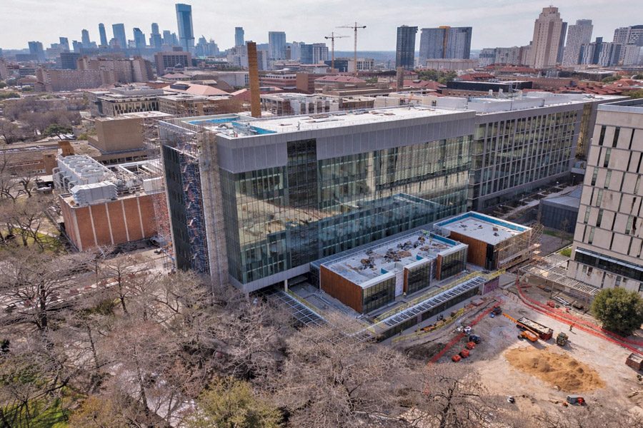
The $316-million Autry C. Stephens Engineering Discovery Building is nearing completion on a narrow, 210,000-sq-ft site along the volatile banks of Waller Creek at the University of Texas at Austin. Set to complete this fall, the facility will host the Hildebrand Dept. of Petroleum and Geosystems Engineering and the McKetta Dept. of Chemical Engineering.
The ACS building was designed by Los Angeles-based CO Architects in association with Austin firm BGK Architects. Vaughn Construction is serving as construction manager.
“This project allows CO Architects to stretch our expertise in cross-disciplinary design,” says Phillip White, associate principal at CO Architects and project manager. “The new research and teaching laboratories will encourage collaboration among UT Austin’s engineering schools, accommodate increasing enrollment and attract top faculty and researchers.”
One of the project’s primary hurdles was anchoring the seven-story research hub along the edge of Waller Creek, a six-mile urban waterway that flows from north Austin through the university campus and downtown. To navigate the high-velocity flood zone and erodible soils, the project team utilized specialized bank stabilization and deep-foundation techniques. This approach not only protects the facility from the 100-year floodplain but ensures the new footprint has zero downstream impact on the creek as it heads toward Lady Bird Lake.

Vaughn Construction mitigated supply-chain delays by resequencing work to maintain the project schedule.
Photo Courtesy J.T. Vaughn Construction LLC
The new buildingreplaces an existing one from the 1940s that was constructed adjacent to Waller Creek and was prone to flooding. “While the [building] footprint closely follows that of the one it replaces, the new structure’s ground floor was raised approximately 12 feet above the floodplain developed by the city of Austin,” says Andrew Labov, principal at CO Architects. That elevation—equivalent to FEMA’s 300‑year floodplain—required significant new fill, as UT barred basement construction.
Fill for the project included crushed limestone aggregates to support the slab on grade, while columns were supported by concrete piers drilled through the compacted fill to bear on a native limestone shelf approximately 5 to 15 ft below the ground floor.
“Labs with 100% outside air don’t get the luxury of recirculation.”
—Sena Esrefoglu, Associate, Shah Smith & Associates
“As the podium of the building will be exposed to occasional flood waters, the foundation walls were developed as architectural board-formed concrete walls, providing an appropriate, robust finished appearance,” says Labov. “The banks of Waller Creek are stabilized by existing mature trees, whose shallow surface roots were extensively surveyed and mapped, allowing our landscape architect and UT arborist to define the ‘no-build zones’ for both the building and sitework that were similarly protected during construction.”
Mark Watts, project manager at Vaughn Construction Co., says the subsurface conditions on this site included layers of clay and gravel in the upper layers, underlain with limestone located roughly 5 to 20 ft below the original grade.
“We built the foundation as a conventional slab on grade placed over about 10 feet of well-compacted structural fill. The ground floor sits approximately 12 feet above the lowest grade,” says Watts. “For heavier loads” conditions, such as structural columns and other concentrated points, the structure is supported on drilled shaft piers bearing into the limestone. The piers embed between 5 and 16 feet into the rock, providing the strength and stability required.”

An early-morning concrete pour formed the podium structure for future academic and collaboration spaces. The project remains on track for summer completion.
Photo Courtesy J.T. Vaughn Construction LLC
The Bridge to Gary L. Thomas
A centerpiece of the campus integration is a pedestrian bridge connecting the Autry C. Stephens building to the Gary L. Thomas Energy Engineering Building. This wasn’t a simple “bolt-on” procedure; it required navigating the structural settling differences between a new seven-story tower and an established structure.
“The bridge connects the two buildings together with large, curved I-beams with an expansion joint at the GLT side of the bridge,” says Labov. “Precast planks form the bottom diaphragm of the bridge with a composite metal deck roof, and a full-height cable net provides fall protection at the bridge, supported by a slender frame of stainless-steel tubes.”
The bridge is supported by and tied to the Stephens building and bears on newly constructed steel haunches added to the GLT building, which were required because the density of underground site utilities adjacent to GLT precluded construction of new columns, says Labov.
This required careful removal of existing unitized curtain wall panels and construction of the haunches projecting from newly reinforced existing beams in GLT. “The new bridge bears on the haunches with a Teflon plate to allow differential movement between the buildings, which required careful detailing of waterproof seismic joints tied into the existing unitized curtain wall assembly,” says Labov.

A full-scale curtain wall mock-up undergoing third‑party performance testing.
Photo Courtesy J.T. Vaughn Construction LLC
The ‘Thematic Neighborhood’
Inside the new building, the labs move away from rigid, siloed rooms toward reconfigurable thematic neighborhoods.
“HVAC systems were designed around the mandate of flexibility and adaptability,” says Labov. “To that end, supply and hazardous-exhaust duct mains are of a uniform size entirely along their length and sized with 20% spare capacity to allow for the addition of new fume hoods anywhere within these chemically intensive laboratories. Mechanical shafts have similar spare capacity for future duct risers that can be installed from steel catwalks suspended within the shafts on each floor.”
Additionally, hazardous gas piping—including toxic and flammable gases—is fed from specialty cylinders stored in dedicated H-3 occupancy rooms on each floor. This system was developed with the university fire marshal and the environmental health and safety department and features an independent leak-detection system linked to the fire alarm. Hazardous piping is suspended from the ceiling, allowing researchers to reconfigure it as the experiments change. It is supported by a heavy-duty clean room grid.
“The banks of Waller Creek are stabilized by existing mature trees.”
—Andrew Labov, Principal, CO Architects
While the piping and ducts provide the physical flexibility, the building’s “brain” required a much more complex setup.
Commissioning the building controls proved to be the most complex task on the project, says Sena Esrefoglu, associate at Shah Smith & Associates. “The most technically demanding system to commission was the reset logic across the building’s control systems,” she says, citing chilled water supplied by the campus plant, hot water temperature, waterside differential pressure and air‑handling unit discharge air temperatures and static pressures. The challenge was heightened by the laboratories’ 100% outside-air design. “You can’t hide inefficiencies,” Esrefoglu says. To manage energy use, the team implemented a trim‑and‑respond static pressure strategy that allows terminal units to signal demand upstream. “Getting these controls strategies dialed in, in a building not yet occupied and without real‑world feedback, was the most demanding part of the green systems commissioning process,” she adds.

Shaft piers extend up to 16 ft below grade, with creek‑facing walls elevating the ground floor roughly 12 ft above the floodplain.
Photo courtesy The University of Texas at Austin
Living Roofs and Commissioning
Sustainability was also a construction driver, with the project currently on track to receive LEED Gold certification. The building envelope and HVAC systems are designed to provide indoor thermal comfort despite a wide range of outdoor temperatures. The main mechanical systems include a mix of traditional [variable air volume] systems, which adjust airflow for temperature control, and chilled beams, which use water to cool or heat spaces more efficiently. These systems work together with highly efficient exterior wall assemblies, including rainscreen assemblies incorporating natural materials such as brick, terra-cotta and limestone. Curtain walls also incorporate fritted glazing to reduce solar loading.
The project preserved existing heritage trees at the south side of the site to provide natural shading for the building. An extensive green roof is provided at the teaching pavilions, incorporating native and adaptive plants to enhance stormwater infiltration and purification. Runoff from the green roof and other roofs on the building are captured in a stormwater vault at the north side of the site.
The building’s structural concrete also has low embodied carbon in comparison to other concrete frame buildings. A carbon analysis was done to identify the potential reductions for the concrete mixes used in the project.
To manage the project’s complexity, the design team used Rhino and Enscape for 3D modeling and Ladybug, a Grasshopper plug-in, to refine passive facade strategies and evaluate glare mitigation to improve occupant comfort.
“Getting these controls strategies dialed in, in a building not yet occupied and without real-world feedback, was … demanding.”
— Sena Esrefoglu, Associate, Shah Smith & Associates
“For our core BIM workflow, Revit was essential for producing accurate construction documents and coordinating precisely with other trades,” says Labov. “Additionally, our laboratory planning team used Matterport 360 photography to document existing spaces, which helped us effectively communicate with end-users and track utilities for specialized equipment. We also managed document coordination and markups through Bluebeam Studio Sessions to streamline collaboration. Ultimately, integrating these tools allowed us to efficiently manage, communicate and produce large volumes of complex project information.”
Watts says his team leveraged a combination of digital modeling tools to coordinate work and execution across all trades and ensure accuracy in the field. “Each trade partner developed and modeled their systems in platforms such as AutoCAD, Autodesk Revit, Autodesk Civil 3D and Tekla Structures,” he says. “We combined the models inside Autodesk Construction Cloud and used Navisworks to identify clashes, review constructibility and resolve issues before anyone stepped on site. This approach enabled us to coordinate not only building systems, but also site conditions and existing infrastructure to include utilities and existing tie-ins.”
The project is currently about 92% complete, with most of the building enclosed. Envelope testing is in progress while terra-cotta rainscreen cladding and green roof/paver systems are being installed. The focus of the remaining interior fit-out is on installation of laboratory casework, completion of finish systems as well as the testing, balancing and commissioning of systems.
Sitework remaining includes landscape, irrigation and hardscape in preparation for a custom cast-in-place sculpture by Maya Lin, which will be formed and placed by the contractor.
Other members of the project team include Shah Smith & Associates, MEP engineer; Datum Rios, structural engineer; GarzaEMC, civil engineer; Ten Eyck Landscape Architects and Lionheart, landscape architects; KGM Architectural Lighting, lighting designer; and Buro Happold, sustainability consultant.