
To achieve high current density without significant current heating effects, we fabricated micro-devices (Fig. 2a) capable of reaching a current density of jz ~5 × 10⁷ A/m2 with an applied current of Iz = 200 μA. Fig. 2c shows the AMR profile (i.e. azimuth angle φ dependence) of the first-harmonic component of interlayer resistivity \({\rho }_{zz}^{\omega }\) at 1.5 K at 12 T. As a result of precise alignment of the field perpendicular to the c axis using a two-axis rotation probe, we observed the four-fold φ dependence of \({\rho }_{zz}^{\omega }\). There, \({\rho }_{zz}^{\omega }(\varphi )\) shows narrow dips for B|| [110] and \([\overline{1}10]\) (φ = 0°, 90°, ⋯) while it shows broad peaks for B|| [100] and [010] (φ = 45°, 135°, ⋯), as reported previously45,46. The observed four-fold symmetry of \({\rho }_{zz}^{\omega }(\varphi )\) is consistent with the four-fold rotoinversion symmetry of the Fermi surfaces at jz = 0, since \({\rho }_{zz}^{\omega }(\varphi )\) involves integration over the full kz range (see Methods for a theoretical expression of the first-harmonic component of conductivity). Intuitively, the direction of the current-induced nematic deformation switches by 90° depending on the sign of jz, and its overall effect on \({\rho }_{zz}^{\omega }(\varphi )\) averages out, yielding four-fold symmetry in the linear transport. In contrast, the second-harmonic component of interlayer resistivity \({\rho }_{zz}^{2\omega }(\varphi )\) exhibits distinct two-fold symmetry: sharp dips are located at φ = 0°, 180° (B||[110], \([\overline{1}\overline{1}0]\)), while sharp peaks are located at φ = 90°, 270° (\({{{{\bf{B}}}}}\parallel [\overline{1}10]\), \([1\overline{1}0]\)). This clearly indicates that the valleys A and B are non-equivalent when nonzero jz is applied, breaking the four-fold symmetry in the nonlinear transport. Reflecting that the deformation of each valley is driven by current, the peak height of \({\rho }_{zz}^{2\omega }\) (denoted by \(\Delta {\rho }_{zz}^{2\omega }\) in Fig. 2d) is almost proportional to jz (Fig. 2e). It should be noted here that essentially the same two-fold symmetric \({\rho }_{zz}^{2\omega }(\varphi )\) was observed in a microfabricated device with a different surface orientation (Fig. S3), indicating that the present results are independent of the crystal cutting geometry.
The profile of \({\rho }_{zz}^{2\omega }(\varphi )\) strongly depends on magnetic field (Fig. 3b). At 2 T, it exhibits a sine-like curve with two-fold symmetry. However, with increasing field, the dip (peak) structures located at φ = 0°, 180° (φ = 90°, 270°) progressively evolve, accompanied by the gradual change in the weak background component. As discussed below, the observed variation in \({\rho }_{zz}^{2\omega }(\varphi )\) is explained by the field dependence of \({\rho }_{zz}^{\omega }(\varphi )\); the dips of \({\rho }_{zz}^{\omega }(\varphi )\) (at φ = 0°, 90°, 180°, ⋯) become deeper and narrower with increasing field (Fig. 3a).
Fig. 3: Magnetic-field dependence and fitted results.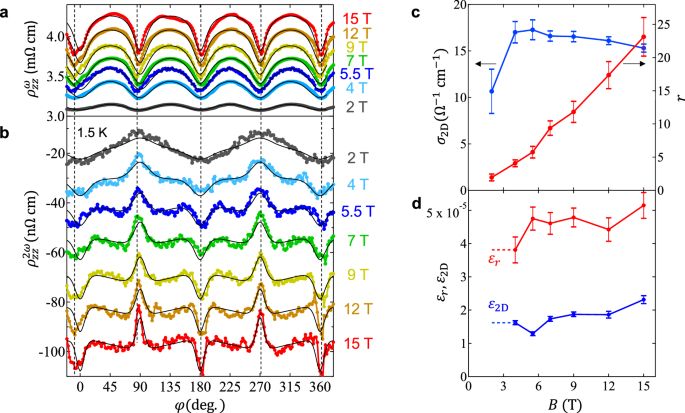
a, b φ dependences of \({\rho }_{zz}^{\omega }\) (a) and \({\rho }_{zz}^{2\omega }\) (b) for SrMnBi2 at 1.5 K for Iz=200 μA for various magnetic fields. The solid curves are the fitted results of the experimental data on the basis of the empirical equation (see the main text). c, d Magnetic-field (B) dependence of the fitted parameters. σ2D (c) and r (c) represent the parameters of AMR, determined by fitting \({\rho }_{zz}^{\omega }\) [Eq. (1)]. ε2D (d) and εr (d) represent the current-induced variations of σ2D and r, respectively, determined by fitting \({\rho }_{zz}^{2\omega }\) [Eq. (5)]. The error bars indicate the uncertainties arising from the fitting.
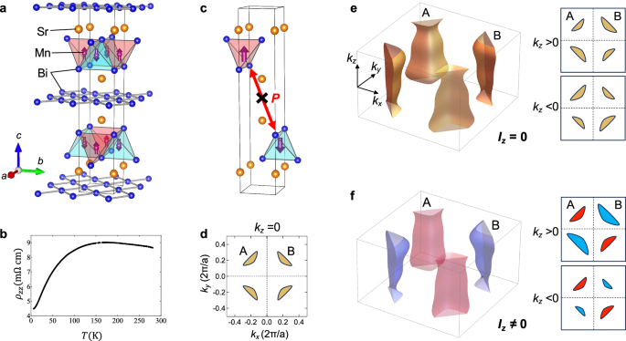
To formulate the relation between \({\rho }_{zz}^{2\omega }(\varphi )\) and \({\rho }_{zz}^{\omega }(\varphi )\), we here employ a phenomenological model of interlayer magnetoconductivity \({\sigma }_{zz}\,(=1/{\rho }_{zz}^{\omega })\) taking account of the in-plane anisotropy of quasi-2D Dirac valley (Fig. 1d)45,46,47:
$${\sigma }_{zz}(\varphi )=\frac{2{\sigma }_{{{{{\rm{2D}}}}}}}{1+r{\cos }^{2}\varphi }+\frac{2{\sigma }_{{{{{\rm{2D}}}}}}}{1+r{\cos }^{2}(\varphi+\pi /2)}+{\sigma }_{3D},$$
(1)
where σ2D (σ3D) is the relative contribution of each quasi-2D Dirac valley (all 3D Fermi surfaces from the parabolic bands)45,46. r is the anisotropic factor of magnetoconductivity, resulting in the maximum (minimum) conductivity for the field along the shorter (longer) axis of the elliptic Dirac valley. Note here that the first (second) term corresponds to the contribution from the valley A (B), which gives σzz peaks, i.e. \({\rho }_{zz}^{\omega }\) dips at φ = 90°, 270° (φ = 0°, 180°). The experimental profiles of \({\rho }_{zz}^{\omega }(\varphi )\) at various magnetic fields are nicely fitted by Eq. (1), as denoted by solid curves in Fig. 3a. The fitted values of r and σ2D are summarised in Fig. 3c. Reflecting the deeper and narrower dips in \({\rho }_{zz}^{\omega }(\varphi )\) at higher fields, the r value monotonically increases with increasing field, whereas the σ2D is almost independent of field (the same is true for σ3D, see Fig. S2). These fitted results are consistent with those reported in the literatures45,46.
We now take account of the impact of the current-induced nematicity on Eq. (1). Considering that the valleys A and B are non-equivalent in the presence of jz, the nematicity can be incorporated as current-induced changes in r and σ2D as follows
$$r\to r(1\pm {\epsilon }_{r}),$$
(2)
$${\sigma }_{{{{{\rm{2D}}}}}}\to {\sigma }_{{{{{\rm{2D}}}}}}(1\pm {\epsilon }_{{{{{\rm{2D}}}}}})$$
(3)
where ϵr(∝jz) and ϵ2D(∝jz) are dimensionless variations in r and σ2D, respectively. Note here that the + sign corresponds to the first term (valley A) in Eq. (1), while the − sign corresponds to the second term (valley B) in Eq. (1). The resultant variation in σzz is given to the first order of ϵr and ϵ2D by (see “Methods”)
$${\sigma }_{zz}(\varphi )\to {\sigma }_{zz}(\varphi )+\delta {\sigma }_{zz}(\varphi ),$$
(4)
where
$$\delta {\sigma }_{zz}(\varphi )= – 2{\sigma }_{{{{{\rm{2D}}}}}}r\left\{{\left(\frac{\cos \varphi }{1+r{\cos }^{2}\varphi }\right)}^{2}-{\left(\frac{\cos (\varphi+\pi /2)}{1+r{\cos }^{2}(\varphi+\pi /2)}\right)}^{2}\right\}{\epsilon }_{r} \\ +2{\sigma }_{{{{{\rm{2D}}}}}}\left\{\frac{1}{1+r{\cos }^{2}\varphi }-\frac{1}{1+r{\cos }^{2}(\varphi+\pi /2)}\right\}{\epsilon }_{{{{{\rm{2D}}}}}}$$
(5)
Since ϵr and ϵ2D are proportional to jz, δσzz is also proportional to jz, corresponding to the nonreciprocal component of the interlayer conductivity. By converting the nonreciprocal conductivity to resistivity using the relation \({\rho }_{zz}^{2\omega }=-\frac{\delta {\sigma }_{zz}}{{({\sigma }_{zz})}^{2}}\) (see “Methods”), we fit the experimental \({\rho }_{zz}^{2\omega }(\varphi )\) profiles at various fields, as shown in Fig. 3b. For this fitting, ϵ2D and ϵr were treated as adjustable parameters, while σ2D and r were fixed to the values obtained from fitting \({\rho }_{zz}^{\omega }(\varphi )\) at each field (Fig. 3c). The experimental \({\rho }_{zz}^{2\omega }(\varphi )\) profiles are well reproduced by Eq. (5) regardless of field, as indicated by the solid curves in Fig. 3b. This demonstrates that the field dependence of \({\rho }_{zz}^{2\omega }(\varphi )\) arises solely from the field dependence of \({\rho }_{zz}^{\omega }(\varphi )\). The extracted values of ϵ2D and ϵr are nearly field-independent and are of the order of 10−5 (Fig. 3d). Consequently, the magnitude of current-induced nematicity is estimated to be of the order of 10−5 for jz ~5 × 10⁷ A/m2 (Iz = 200 μA). In the previous study, current-induced lattice displacement was measured in EuMnBi2, where the largest strain was ~1.4 × 10⁻⁸ at jz ~4 × 10⁴ A/m2 at the lowest temperature36. This corresponds to the strain of ~2 × 10⁻⁵ at jz ~5 × 10⁷ A/m2 (the same jz used in this study). Thus, the nematicity estimated from the AMR profile is of the same order of magnitude as that revealed by the lattice displacement measurements.
Here, we discuss the temperature dependence of ρ2ω(ϕ). The amplitude of the ρ2ω(ϕ) peaks and dips decreases with increasing temperature and nearly vanishes above 30 K (Fig. S4d), which is well below the Néel temperature TN = 295 K40. This arises primarily from the suppression of the AMR \({\rho }_{zz}^{\omega }(\phi )\) at elevated temperatures (Fig. S4c), since \({\rho }_{zz}^{2\omega }(\phi )\) originates from the current-induced modulation of \({\rho }_{zz}^{\omega }(\phi )\). Additionally, a decrease in the current-induced nematicity (i.e. ϵ2D and ϵr) with increasing temperature, as was previously reported in the lattice displacement measurements in EuMnBi236, may further contribute to the more rapid suppression of ρ2ω(ϕ) compared to \({\rho }_{zz}^{\omega }(\phi )\). These results suggest that the temperature dependence of ρ2ω(ϕ) involves multiple underlying mechanisms.
Finally, we demonstrate the detection and control of magnetic domains in the present \({{{{\mathcal{PT}}}}}\)-symmetric antiferromagnet. Fig. 4c, d show the profiles of \({\rho }_{zz}^{2\omega }(\varphi )\) for the two adjacent devices #1 and #2, respectively, after cooling from room temperature without applying any field or current. Notably, the positions of the sharp peaks and dips of \({\rho }_{zz}^{2\omega }(\varphi )\) are reversed between #1 and #2, apart from the relatively large background component in #2. This clearly indicates that the sign of ϵr and ϵ2D, i.e. the domain of antiferromagnetic order, differs between the two devices, even within the same micro-fabricated crystal (inset to Fig. 4c, d).
Fig. 4: Electric-magnetic control of the nonpolar \({{{{\mathcal{PT}}}}}\)-symmetric antiferromagnetic order.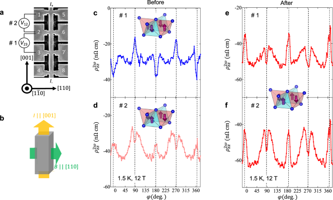
a SEM image of the neighbouring devices. The interlayer resistivity in device #1 was measured between terminals 2–3, while in device #2, it was measured between terminals 1–2. b Schematic showing the direction of the electric current (I) along [001] and the magnetic field (B) along [110] for domain poling. c, d φ dependence of \({\rho }_{zz}^{2\omega }(\phi )\) in devices #1 (c) and #2 (d) at 1.5 K and 12 T for Iz = 200 μA before domain poling. e, f Corresponding \({\rho }_{zz}^{2\omega }(\phi )\) profiles for devices #1 (e) and #2 (f) after domain poling by current-field cooling, showing an inversion of the peak and dip positions in device #1. The insets illustrate the domain of antiferromagnetic order in the Mn-Bi layers of each device.
To align the domains, we employed a poling procedure conducted above TN. Symmetry analysis predicts that the domains of \({{{{\mathcal{PT}}}}}\)-symmetric antiferromagnetic order in this nonpolar system can be aligned by applying an electric current and a magnetic field orthogonal to each other, as illustrated in Fig. 4b (see discussions below)48. To achieve this experimentally, we applied a current of 1 mA (jz ~3 × 10⁸A/m2) along [001] and a field of 18 T along [110] at 305 K (>TN), and then cooled the sample to 4.2 K. After poling, we repeated the AMR measurements at 1.5 K and 12 T. In device #1, the peak and dip of \({\rho }_{zz}^{2\omega }(\varphi )\) are inverted compared to the previous measurement without poling (Fig. 4e). On the other hand, in device #2, the magnitude of the peak and dip of \({\rho }_{zz}^{2\omega }(\varphi )\) is enhanced while keeping their positions (Fig. 4f). These results indicate that the antiferromagnetic domains in both devices were aligned to the original domain in device #2 through the poling procedure, thereby demonstrating electric-magnetic manipulation of the nonpolar \({{{{\mathcal{PT}}}}}\)-symmetric antiferromagnetic order. We note that the gradual background component in device #2 does not change before and after the poling, suggesting that it may arise from pinned domains and/or other extrinsic effects.
We next discuss the mechanisms underlying this control of antiferromagnetic domains in the present material. Recently, several current-driven domain control methods have been developed for metallic antiferromagnets, although their variety remains limited49,50. For \({{{{\mathcal{T}}}}}\) odd antiferromagnets with spin-split bands3, conventional control mechanisms, similar to those in ferromagnets, can be employed. Examples include spin-orbit torque switching at the interfaces of artificial heterostructures12,13,14. In contrast, the control mechanisms for \({{{{\mathcal{PT}}}}}\) -symmetric antiferromagnets with spin-degenerate bands are significantly more intricate. In the polar systems, such as CuMnAs15,27 and Mn2Au51, current-induced switching was achieved via the sublattice-dependent spin-momentum locking52,53. However, in nonpolar systems like SrMnBi2, the absence of polarity (p-wave) in momentum space prevents the domain switching using current alone. Instead, the higher-order f-wave polarity in momentum space can be utilised. To this end, we have applied an in-plane field, effectively rendering the system polar and enabling current-induced switching. This combined electric and magnetic manipulation of \({{{{\mathcal{PT}}}}}\) -symmetric antiferromagnetic domains provides a novel protocol distinct from those employed for \({{{{\mathcal{T}}}}}\) -odd or polar antiferromagnets currently under active investigation.
For \({{{{\mathcal{PT}}}}}\)-symmetric antiferromagnets, a variety of nonlinear conduction phenomena, classified by the dependence on the relaxation time, were theoretically predicted23. In this context, our study focuses on the Drude component to provide direct evidence of current-induced electronic nematicity, manifested as nonlinear interlayer conduction along the high-symmetry c−axis under a magnetic field. In addition, SrMnBi2 is also predicted to exhibit other types of nonlinear in-plane conduction along the ab plane, such as the (zero-field) nonlinear Hall effect arising from the quantum geometric component27,28,29. Exploring in-plane nonlinear responses may thus represent an important direction for future research in nonpolar \({{{{\mathcal{PT}}}}}\)-symmetric antiferromagnets.
To conclude, we report the observation of current-induced electronic nematicity in the nonpolar \({{{{\mathcal{PT}}}}}\)-symmetric antiferromagnet SrMnBi2 by measuring the nonreciprocal angular magnetoresistance (AMR) effect. The breaking of the original four-fold rotoinversion symmetry is detectable via the valley degrees of freedom of Dirac fermions in the Bi square net, which is adjacent to the Mn-Bi tetrahedral layer exhibiting \({{{{\mathcal{PT}}}}}\)-symmetric antiferromagnetic order. By employing a phenomenological model of the AMR effect attributed to elliptic Dirac valleys, we quantitatively reproduce the two-fold nonreciprocal AMR signal, demonstrating the current-induced lifting of the valley degeneracy. The layered structure incorporating a Dirac fermion layer in this material offers a novel platform for the electrical control of valleys by the \({{{{\mathcal{PT}}}}}\)-symmetric antiferromagnetic order. Our findings may pave the way for developing unconventional spintronic and valleytronic devices, thereby broadening the scope of antiferromagnetic spintronics.