
Electrically tunable cavity-coupled IXs
Several TMDC combinations provide type-II alignments with IXs3,6. In our work, we chose MoSe2/WSe2 as an exemplary platform owing to the strength and the low inhomogeneous broadening of its interlayer PL emission at cryogenic temperatures6, together with the ultra-long lifetimes of the hosted IXs3. This choice was further motivated by the extensive literature on this platform, specifically concerning its angular emission pattern34 and optical transition dipoles18,33. We note that layer-hybridized species in WSe2 bilayers are also known to possess efficient PL emission and tunable character11, although their momentum-indirect nature could prove challenging for the study of tunable cavity coupling, which is out of the scope of this work. Other homobilayer TMDCs are characterized by momentum-direct hybrid species with high oscillator strengths15,16, but these do not constitute the lowest-energy transition, resulting in relatively weak PL emission17. Furthermore, owing to their intrinsic nature, the lifetimes of all these species are orders of magnitude lower (<1 ns) than type-II IXs.
To exploit the quantum-confined Stark effect of IXs, we have fabricated dual-gated MoSe2/WSe2 bilayer structures fully encapsulated by hexagonal boron nitride (hBN), which we embedded in planar λ/2 cavities based on DBR mirrors35 (Methods and Fig. 1a). We used the optical transfer-matrix method to design the full stack and predict the energy mode and the quality factor (Q) of our structure. In Supplementary Note 4, we present more information on the chosen configuration of the DBR mirrors based on the losses in our system. The optical micrograph of the main structure used in this work (device A) is reported in Fig. 1c. We fabricated another structure (device B) to confirm our findings, and its optical micrographs are reported in Supplementary Note 1.
Fig. 1: Electrically tunable cavity-coupled IXs.
a, Schematic of the device structure, comprising a MoSe2/WSe2 heterobilayer encapsulated with hBN, with bottom and top graphene (Gr) layers. Bottom (VBG) and top (VTG) gate voltages are applied to the graphene layers, respectively, while the TMDC flakes are grounded (GND). The cavity consists of the bottom and top SiO2 layers and the van der Waals heterostack. The bottom DBR mirror comprises 12 pairs of Ta2O5–SiO2 layers, providing a wide reflectance window in the 800–1,000 nm range (Supplementary Fig. 2). The top DBR mirror consists of six pairs of SiO2–Si3N4 layers, each precisely matched at the optical path to correspond to half of the selected wavelength (λ/2). b, Illustration of type-II IXs in MoSe2/WSe2 in the condition of weak coupling with an applied electric field. c, Optical micrograph of device A, with highlighted flakes of WSe2 (blue), MoSe2 (red), bottom graphene (white) and top graphene (black). Scale bar, 10 µm. d, PL spectra (bottom) obtained from IXs at different electric fields in the full-cavity device A, excited by a laser power of 50 nW. In the vicinity of Ez ≃ −120 mV nm−1, the exciton emission is aligned with the differential reflectance (DR) dip (top). A notable enhancement of the collected PL intensity is present in the condition of exciton-cavity matching. This dataset is a subset of the full field-dependent spectra shown with a linear scale in Fig. 2a.
Before growing the top DBR pairs, we characterized the field-tunable emission of IXs and their dynamics in our platform (Supplementary Note 2). The lifetime of IXs on bottom DBR substrates is monotonically tuned with respect to the electric field Ez owing to the modulation of the electron–hole wavefunction overlap14. Then, we have designed our cavity so that its resonant energy falls within the same range as the tunable IX emission energy. After the top DBR deposition, we achieved an average quality factor of Q ~70 with variance ~30 within the whole double-gated heterostack and a cavity peak mode centred around 1.389 eV (Supplementary Note 3). In Fig. 1d, we show the field-tunable PL spectra obtained by modulating the detuning between the exciton (EIX) and cavity (EC) modes. In particular, from Fig. 1d, we extract an enhancement of the maximum IX peak intensity of a factor ~50 for cavity-coupled IXs (EIX ≈ EC) with respect to uncoupled ones (EIX < EC).
Tunable inhibition of IX spontaneous emission rate
Figure 2a shows the quantum-confined Stark effect of the IXs in our platform, excited by a pulsed picosecond diode laser (1.93 eV) with an average power of 50 nW and a repetition rate of 1 MHz. By fitting the Stark shift of the main IX peak, we estimate a dipole length of 0.5 nm, in agreement with previous reports14,36. We observe a sizable enhancement of the recorded PL as the exciton-cavity detuning is decreased. Furthermore, an apparent energy jump can be observed with the detuning at its minimum in Fig. 2b. For increasing electric field magnitudes with respect to the nominal resonance (Ez < −130 mV nm−1), the maximum energy peak position reverts back to the trend dictated by the linear Stark effect. This is attributed to the field-dependent tuning of our IX emission from lower to higher energies, causing the maximum PL peak to appear as shifted when the cavity transparency dip is reached (Supplementary Note 6).
Fig. 2: Tunable enhancement of emission and lifetime from cavity-coupled IXs.
a, IX PL spectra as a function of the applied vertical electric field Ez, obtained by exciting the structure with a 50 nW laser power. The dashed line corresponds to the linear quantum-confined Stark effect of IXs. A region of higher intensity is observed at the vicinity of 1.38 eV, corresponding to the cavity mode energy (Fig. 1d). We further show the field-dependent spectra in a waterfall plot in Supplementary Note 2, comparing it with the half-cavity case to better highlight the behaviour of the IX peak when entering the cavity transparency dip. b, Field-tunable position of the highest-emitting exciton peak energy (red). A shift of the brightest peak is found around –80 mV nm−1 owing to entrance of the IX tail into the transparency window. The shift around –120 mV nm−1 represents the first exciton-cavity resonance condition. The cavity mode is highlighted by the differential reflectance dip (grey). c, Total integrated IX PL intensity (red) and lifetime (blue) as a function of Ez. Both intensity and lifetime exhibit a gradual increase for Ez < −50 mV nm−1, with a sharp peak at Ez ≃ −120 mV nm−1 followed by a gradual decrease. At resonance, as indicated by the dashed grey line, a 50-fold enhancement is observed for the integrated IX intensity, together with a 5-fold increase in lifetime.
We will hereafter refer to the structure without the top SiO2 and top DBR mirrors as the ‘half cavity’, and the complete device (Fig. 1a) as the ‘full cavity’ structures. Figure 2c shows the field-dependent integrated PL intensity and lifetime of the interlayer IX peaks in the full-cavity structure. As detailed in Supplementary Note 6, in the half-cavity structure, we observe a smooth decreasing PL intensity trend with respect to the applied electric field. However, in the full-cavity structure, we measured an enhancement of intensity for electrostatic fields that minimize exciton-cavity detuning. In particular, an increase in PL emission is observed for fields Ez ≤ −50 mV nm−1, with a peak around Ez ≃ −120 mV nm−1 followed by a gradually decreasing tail. To understand the asymmetric trend of the integrated PL intensity recorded from our system, we used optical transfer-matrix method simulations of the far-field emission of ideal dipoles in the energy range of our IXs (Methods). As further discussed in the following sections and in Supplementary Note 9, we ascribe such asymmetry to the angle-dependent emission of cavity-coupled in-plane IX optical transition dipoles.
Furthermore, we measured the field-dependent dynamics of our interlayer ensembles by time-resolved PL, as shown in Fig. 2c. Before the top cavity growth, we recorded lifetimes in the range of tens of nanoseconds. In particular, the trend of decreasing lifetime with increasing Ez in the half-cavity structure (Supplementary Fig. 2) is directly related to the modulation of the electron–hole wavefunction overlap by the quantum-confined Stark effect, as in previous reports11,14,37. In the full-cavity structure, we observe a sharp increase of the IX lifetime under the exciton-cavity matching condition, with a fourfold increase with respect to the half-cavity excitons (Supplementary Fig. 8d). Therefore, our structure exhibits a combined enhancement of both the extracted PL intensity and the lifetime of IX ensembles when tuned to the cavity resonance.
We explain the obtained lifetime enhancement by a Purcell inhibition of the IX spontaneous emission rate (that is, increase in IX lifetime). The main factors that can contribute to a sizable Purcell inhibition are spatial misalignment38, spectral detuning39 and the depletion of photonic states owing to the optical microcavity40. Since we use a planar λ/2 cavity, the spatial detuning can be assumed to be negligible, while the quantum-confined Stark effect allows us to minimize the spectral detuning. By comparing with the half-cavity structure (Supplementary Fig. 8d), we confirm that the observed lifetime enhancement is a result of the modulation of the radiated photonic mode density, thus allowing a nontrivial simultaneous enhancement of the collected PL intensity. Therefore, we attribute the observed lifetime trend to the discontinuity of photonic mode density at the resonant condition for weakly coupled in-plane IX transition dipoles41,42 (Supplementary Note 9).
Field-effect tuning of momentum-resolved IX emission
To investigate the radiation pattern of cavity-coupled IXs in our monolithic DBR system in momentum space, we performed Fourier imaging of the back-focal-plane (BFP) PL emission with respect to the applied electric field. Figure 3a–c shows the momentum-resolved emission of IXs at three different fields. kx and ky represent the x and y components of the in-plane photon wavevector k0 sin θ, where θ is the emission angle and k0 is the photon wavevector in air.
Fig. 3: Dispersion of cavity-coupled IXs in momentum space.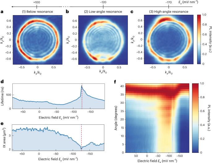
a–c, Momentum-resolved IX emission obtained by BFP PL spectroscopy at electric field strengths of Ez ≃ 100 mV nm−1 (a), −120 mV nm−1 (b) and −170 mV nm−1 (c), respectively. All measurements were obtained under a 50 nW laser excitation. High-momentum components dominate the signal for a and c, while low-momentum PL emission arises in the case of b. The complete field-dependent BFP dataset is shown in Supplementary Video 1. BFP images are normalized at each electric field to show the different components in momentum space at all exciton-cavity detuning conditions. d,e, Field-dependent lifetime (d) and effective IX diffusion area (e). The data in d are an extension of that shown in Fig. 2c. In agreement with previous reports11,13, we define the IX effective diffusion area as the region of the IX emission cloud in space with PL intensity above 1/e of its maximum. The IX emission cloud is recorded by a CCD camera, as described in Methods. The dashed red lines indicate the electric field value of lowest IX effective diffusion area, as well as highest PL intensity and lifetime. f, Field-dependent angular emission is obtained by radially averaging the measured BFP images at each electric field. The recorded PL emission is normalized at each electric field. The enhancement of the low-angle emission components is observed for electric fields in the range −130 mV nm−1 < Ez < −50 mV nm−1, corresponding to region (2).
We define three main regions of the applied electric field: (1) below resonance (Ez > −50 mV nm−1), (2) low-angle resonance (−50 > Ez > −130 mV nm−1) and (3) high-angle resonance (Ez ≤ −130 mV nm−1). We observe a dominant high-angle emission in the momentum dispersion below cavity resonance (Ez ≈ 100 mV nm−1; Fig. 3a). We note that a non-negligible signal around zero momentum is also present. Moreover, we observe a sizable enhancement of low-angle emission when in the exciton-cavity mode matching condition (Ez ≈ −120 mV nm−1; Fig. 3b), concurrently with the recorded enhancement of both PL intensity and lifetime (Fig. 3d). When further increasing the applied electric field magnitude, the emission pattern reverts back to a situation of dominant high-angle emission, as shown in Fig. 3c (Ez ≈ −170 mV nm−1).
To further highlight the field dependence of the momentum-resolved emission in our system, we calculate a radial average of the k components in the BFP images with respect to Ez (Fig. 3f and Supplementary Video 1). These results reveal a change in the angular emission of cavity-coupled IXs in correspondence with the enhancement of their emitted PL intensity and lifetime. Moreover, as the electric field decreases from −50 mV nm−1 to −130 mV nm−1, time-integrated imaging of the spatial distribution of IX emission shows a notable reduction in the IX diffusion area and simultaneous increase of IX lifetime, as illustrated in Fig. 3d–f. This coincides with a radiative enhancement of low-momentum IXs, suggesting a potential mechanism for photonic IX localization.
WSe2/MoSe2 heterobilayers are known to host a rich excitonic platform owing to the moiré potential arising from the atomic registry between the two layers18,33,43,44. In particular, the moiré superlattice in incommensurate WSe2/MoSe2 heterobilayers is expected to give rise to both in-plane and out-of-plane IX transition dipoles of comparable strength18, where only the in-plane transition dipoles are expected to couple optimally with planar cavities39. Thus, different IX species with different group velocities and emission profiles are expected to coexist. The exciton group velocity vg can be defined based on the Wannier function approach for both monolayer TMDCs45 as well as for IXs in moiré heterobilayers46. Thus, we explain our results by the enhancement of the emission of low-vg IXs when in resonance, inducing an effective IX cloud area reduction with respect to off-resonance or high-angle resonance conditions. In fact, at resonance, the IX species with lower group velocity must preferentially couple into low-angle (low-momentum) optical modes45. When the electric field is between −130 mV nm−1 and −160 mV nm−1, the visualized IX effective diffusion area expands, corresponding with an increase in emission from higher-momentum IXs. Finally, for Ez ≤ −160 mV nm−1, the IX emission momentum remains dominated by high-momentum components, while a pronounced decrease in IX lifetime correlates with the observed decrease in the IX diffusion area.
IX transition dipoles and cavity coupling
To understand the tunability of our cavity-coupled IX emission, in Fig. 4a–c, we show the energy-resolved PL of IXs in our platform with respect to their angular pattern (Methods), obtained from the ky component of the BFP data. In particular, Fig. 4a–c is representative of regions (1) to (3), respectively. The complete energy-resolved field-dependent dataset is shown in Supplementary Video 2, reporting the linear Stark shift of the IX emission in energy and the corresponding evolution of its angular pattern. In region (1), we observe dominant emission at high angles for all IX energies, as previously shown by the corresponding BFP measurements (Fig. 3a). However, for conditions (2) and (3) in Fig. 4b,c, respectively, the emitted intensity follows a quasi-parabolic trend towards higher angles.
Fig. 4: Field-dependent angular emission of IX transition dipoles in an optical microcavity.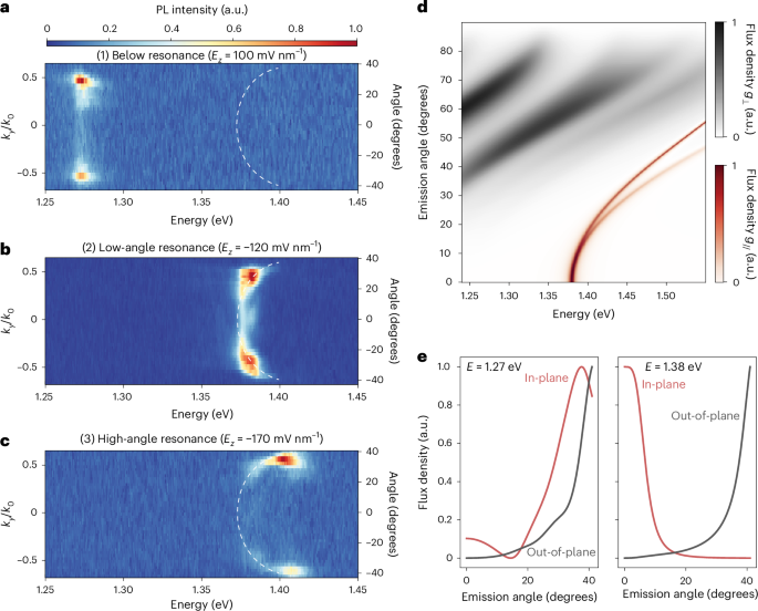
a–c, Energy-resolved IX emission obtained by the ky component of BFP PL spectroscopy at electric fields Ez ≃ 100 mV nm−1 (a), −120 mV nm−1 (b) and −170 mV nm−1 (c), respectively. All measurements were obtained under 50 nW laser excitation. In a, high-angle emissions dominate the signal, with a non-negligible component at low angles. When approaching the resonant condition (b), low-angle emissions are enhanced, with residual components still present at higher angles. Moving towards higher electric fields (c), a progressive quasi-parabolic shift of the emitted PL is observed towards higher angles (Supplementary Video 2). The dashed white lines are guides to the eye following the field-dependent angular dispersion of the IX PL. d, Transfer-matrix simulations of the angular emission pattern of ideal in-plane (g//) and out-of-plane (g⊥) dipoles within our structure with respect to their emission energy. The relative intensity of the emission flux density is normalized for both dipolar species. No coupling condition is achieved for out-of-plane dipoles. Instead, a sharp rise in the in-plane dipole emission is present at the nominal cavity mode (1.38 eV). With increasing energies, the cavity coupling condition is still obtained for higher angles of emission of the in-plane dipole, thus yielding a parabolic trend at low angles, becoming linear at higher energies. e, Left: the emission in the below-resonance range (E ≃ 1.26 eV), retrieved from a linecut in d, shows a non-negligible flux density at low angles (θ < 20°) for the in-plane dipole, followed by a dominant signal at higher angles (θ > 40°). The emission from the out-of-plane dipole gives a sizable flux density at high angles. This is in agreement with the observed emission in a. Right: the emission at exciton-cavity resonance (E ≃ 1.38 eV) is strong in the vicinity of 0° for the in-plane dipole owing to efficient cavity coupling. By contrast, a high-angle signal is still present for the out-of-plane dipole. Thus, the sudden change to 0° emission in the exciton-cavity matching condition of b is related to the selective cavity coupling of in-plane IX transition dipoles. The trend for E > 1.38 eV in d is consistent with the resonance observed in c.
A notable enhancement in the low-angle emission in region (2), together with the quasi-parabolic trend in (2) and (3), is also reported in Supplementary Fig. 9 for another position of the heterostructure in device A, as well as in Supplementary Fig. 11 for device B. We note that no substantial difference is observed at different excitation powers, as shown by the characterization in Supplementary Fig. 9 conducted at 0.9 mW. These results show that the achieved field tunability of the IX angular emission pattern is independent of intrinsic heterostructure region-to-region variations.
To understand the observed energy dispersion of coupled IX emission, we need to consider the presence of both in-plane and out-of-plane transition dipoles in our heterobilayer18, as mentioned in the previous section. In particular, although the IX energy of emission can vary based on the moiré periodicity, an emitting interlayer transition in a given TMDC heterobilayer with little atomic mismatch will feature a non-negligible coupling with in-plane and out-of-plane photon modes, with properties that vary across the moiré cell based on the atomic registry. In the case of WSe2/MoSe2, both spin-singlet and spin-triplet transitions are expected to possess both in-plane and out-of-plane transition dipoles within a moiré cell18. Therefore, we have performed optical transfer-matrix simulations of ideal emitters in our structure comprising both out-of-plane and in-plane optical dipoles as a function of the optical dipole emission energy. In Fig. 4d, we show the emitted intensity flux obtained for a wide range of emission energies, mimicking the energy span covered by our field-tunable interlayer species. At energies lower than the cavity mode (E < 1.38 eV), both in-plane and out-of-plane dipoles give emitted fluxes with maximal intensities at high angles (>30°), as further highlighted in Fig. 4e. The presence of a sizable lobe of the flux density at low angles for the in-plane transition dipole is aligned with the non-negligible signal that we experimentally observe at low momentum off resonance (Fig. 4a). Thus, we attribute the observed emission in the region (1) of the field-tunable BFP measurements to the superposition of both in-plane and out-of-plane IX transition dipoles of different local atomic registries34. By contrast, we observe a sharp increase of the in-plane dipole emission when reaching the cavity mode, as in region (2). Figure 4d shows that, for increasing energies, cavity coupling is achieved for in-plane dipoles at higher angles, exhibiting a parabolic trend in the energy dependence of coupled emission, confirming our observations in region (3). We note that our collection is limited to a partial range of angles (±40°; Methods), which is nonetheless wide enough to be covered by our simulations. In Supplementary Note 8, we mimic the exciton emission energy tunability by convoluting the simulated emission of an in-plane dipole in our structure with Lorentzian broadening. As a result, Supplementary Fig. 14 gives a theoretical representation of the tunable cavity coupling of in-plane IX transition dipoles in our structure.
We note that the large structural changes owing to mesoscopic reconstruction have been shown to strongly impact the spectroscopic signatures of IXs47. While we acknowledge the possibility that bubbles and morphological inhomogeneities could induce mesoscopic reconstructions in our samples, any arbitrary IX transition dipole can always be described as a superposition of two orthogonal transition dipoles48 (Supplementary Note 9), thus further motivating our theoretical treatment (Fig. 4d). This is corroborated by the qualitatively consistent behaviour of cavity-coupled IXs between different positions within the same device and across different devices (Supplementary Notes 6 and 7). Additional information on the spatial analysis of the IX emissions in device A is provided in Supplementary Note 6.
On the basis of the previous discussion, we explain the sharp increase in emission intensity at exciton-cavity resonance based on the change in the angular emission pattern of weakly coupled in-plane IXs owing to cavity transparency. By contrast, at all electric field strengths, the out-of-plane IX dipoles do not efficiently couple to the cavity modes supported by our structure.