
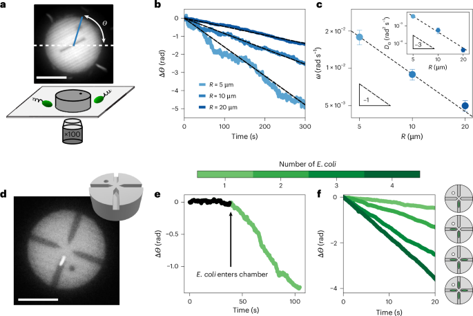
Bacteria are torque dipoles and swim in circles
As our observations were performed near the bottom of a glass capillary, where objects are confined by gravity, we first recapitulate the swimming behaviour of swimming E. coli near a no-slip wall. Swimming E. coli are force- and torque-free. They are accurately represented hydrodynamically by a force dipole21 and a torque dipole: the flagella spinning one way and the body spinning the other way to balance the torque. In effect, swimming E. coli are hydrodynamically attracted to solid walls by the image charge of the force dipole22 and swim in (clockwise) circles as a result of the opposing shear forces induced by the torque dipole23 (Supplementary Fig. 2a).
Experimental procedure
We now study the dynamics of 3D-printed discs, dubbed ‘pucks’, in the presence of swimming bacteria. The pucks were printed with radius R = 5 μm, 10 μm or 20 μm and constant height ~6 μm using a two-photon-polymerization printer (NanoOne, Upnano) (Fig. 1a and Supplementary Information). After printing and development, they were dispersed in a solution of 5% F 108 surfactant to prevent aggregation and were subsequently concentrated (Supplementary Fig. 1). The pucks were added to a suspension of swimming E. coli in a motility medium and sealed in a glass capillary (Methods). The concentration of swimming E. coli (ρB) was adjusted before the experiment and is described in each section. The pucks sedimented. They sat at the bottom of the capillary and interacted with swimming E. coli (Fig. 1a). We carried out our observations by fluorescence microscopy using the autofluorescence of the nanoprinting resin and the green fluorescent protein (GFP) tag of the bacteria (Supplementary Information). A dot and a line were added to the design so that we could track the orientation Θ(t) of the pucks (Fig. 1a).
Collisions with E. coli swimming clockwise rotate symmetric discs
We first observed the dynamics of simple pucks—thick discs—in a bacterial bath of concentration ρB = 6 × 10⁸ cells per millilitre. The clockwise rotation of aggregates was observed in ref. 20. Bacteria did not cross underneath the discs, as visible from fluorescence microscopy. They collided with the perimeter of a puck and deflected (Supplementary Video 1 and Supplementary Fig. 2b). The discs exhibited noisy dynamics at short times, reminiscent of the high effective temperature of the bacterial bath5,6,7,20 (Fig. 1c inset and Supplementary Fig. 3). Over the course of minutes, the pucks displayed a slow but perceptible clockwise rotation for all tested radii R = 5 μm, 10 μm and 20 μm (Fig. 1b). We quantified these observations by tracking the angle Θ(t) (Fig. 1a) and computing the rotation rate ωR of the pucks from a linear fit of Θ(t). We found that ωR ∝ 1/R (Fig. 1c), as previously found for colloidal aggregates in bacterial baths20. In brief, the curved trajectories of the swimming bacteria, as exemplified in Supplementary Fig. 2, lead to asymmetric collisions with the puck. These collisions produce a net torque and persistent rotation, in the absence of shape asymmetry (see ref. 20 for details of this toy model and Supplementary Section 2). The rotation is driven by forces on the perimeter of the disc, a mechanism akin to conventional bacterial machines (for example, see refs. 9,10,12,16,17), whereby a shape asymmetry was used to rectify the motion of E. coli and power rotation. In the present experiment, the asymmetry arises from the chirality of the clockwise trajectories of the E. coli swimming above the solid interface of the glass capillary.
We estimate the effective tangential force F* resulting from collisions of the puck with swimming bacteria as \({F}^{* }=\frac{\omega }{{M}_{\Theta }R}\approx\) 0.006–0.06 pN, based on the reported rotation rate ω ≈ 10−3–10−2 rad s−1 (Fig. 1c) and independent measurements of the rotational mobility MΘ of the puck (Supplementary Fig. 4). This value of F* is markedly smaller than the effective pushing force per cell measured for micromotors powered by swimming E. coli, F ≈ 0.2 pN (ref. 12), as well as the typical flagellar thrust of E. coli cells21,24. This reflects the minimal rectification proportional to ℓB/Rc arising from the collisions of the curved trajectories with the puck perimeter, where Rc ≈ 50 μm is the radius of curvature of the trajectories and ℓB the bacteria length, as discussed in Supplementary Section 2. The effect is, however, sufficient to drive persistent rotation over long timescales and control unconventional aggregation20. Notably, our simple model satisfactorily predicts the observed rotation rate when accounting for the collision rate observed in the experiment (Supplementary Section 2).
E. coli in confinement power symmetric discs
In this section, we present a new type of bacterial machine, one that is powered by the torque dipole of individual E. coli confined beneath symmetric discs. The effect is contactless, as it does not have the aforementioned collisions that power conventional bacterial ratchets. Here we present the experimental evidence that led us to unveil this new physical mechanism. We introduce two variants of the circular pucks, each with fixed radius R = 10 μm. Our aim was to confine individual E. coli underneath them. The first kind is a disc with four narrow chambers, placed radially, each terminating near the centre of the puck (Fig. 1d). The second kind has a single narrow channel, open on both ends, along the diameter of the puck (Fig. 2d). We present observations only of pucks where the chambers or channel lie on the bottom substrate, facing down. For the quantitative observations, we suspended the pucks in a dilute bacterial bath (ρB = 3 × 10⁷ cells per millilitre) and investigated their dynamics as they interacted with individual E. coli. Time-lapse data were acquired by spinning-disc confocal fluorescence microscopy (Nikon TI-2 Eclipse, 10 frames per second; Methods). These data were analysed to record simultaneously the position of the centre of mass of the puck, its orientation Θ and the position of an E. coli body confined beneath the puck. Note that only the body of each bacterium was fluorescently labelled and that the flagellum, a floppy tail of length ~6.5 μm (ref. 25), is not visible in the experiments.
Fig. 2: Dynamics of pucks with a single swimming E. coli crossing the channel.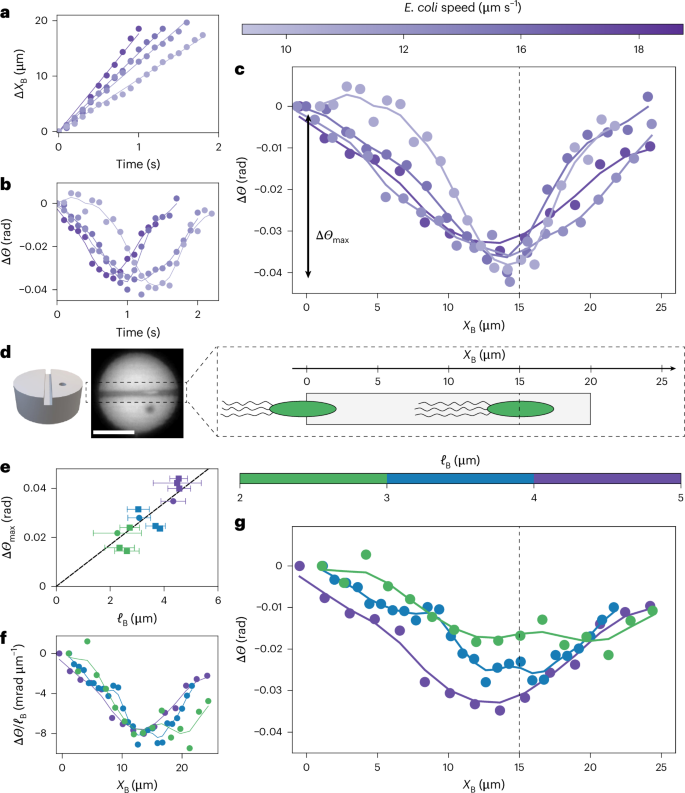
a, Position of swimming E. coli (XB(t)) inside the channel. Different colours indicate different bacteria. The velocity is obtained by a linear fit (solid lines). b, Rotation of the puck, ΔΘ(t) = Θ(t) − Θ(0), as a single swimming E. coli passes through the channel. Different colours indicate different bacteria with different velocities (colour bar). c, The curves ΔΘ(t) from b collapse when represented as ΔΘ(XB), as prescribed by low-Reynolds-number dynamics. ΔΘ(XB) decreases before reversing direction, presenting a characteristic ‘down–up’ shape. The dashed line highlights the location of the minimum: XB = 2R − ℓB ≈ 15 μm. The depth of the down–up shape is denoted ΔΘmax. d, Left: schematic of a puck with a single channel. Middle: image of a puck. Right: schematic representation of E. coli swimming through the channel. The body and flagella are for a puck of radius 10 μm. The dashed line is the dashed line in c. e, Depth of the dip, ΔΘmax, as a function of the body length of E. coli (ℓB). Each data symbol represents a crossing event by a bacterium (N = 12 events). Error bars represent the standard deviation for the bacteria length (ℓB) determined by fluorescence microscopy. f, Plot of ΔΘ(XB)/ℓB showing the collapse of the first part of the down–up shape, as predicted by the model. g, Rotation of the puck, ΔΘ(XB), for E. coli of different sizes (ℓB). The data do not collapse, in contrast to bacteria moving at different speeds (c). For larger E. coli, the minimum is deeper and occurs earlier. In all panels, solid lines are a Gaussian extrapolation of the experimental data (solid dots). Scale bar, 10 μm.
We begin by describing the dynamics of the pucks with chambers following the entry of an E. coli into the chamber. The puck has four chambers, each with a square cross section (2 μm × 2 μm), placed radially and ending at a distance d ≈ 0.5 μm from the centre of the disc (Fig. 1d). The chambers are large enough for an E. coli to enter but too narrow for it to reverse direction; effectively, the E. coli becomes confined underneath the puck, while its body and flagella continue to spin. As soon as an E. coli positions itself in a chamber, the rotation rate of the puck increases drastically to ω ≈ 3 × 10⁻² rad s−1, while always remaining clockwise (Fig. 1e). This was an unexpected finding as the chambers were designed to be radially aligned, thus suppressing any contribution to the torque from direct collisions with the walls. A simple estimate of the rotation rate of a puck arising from a single E. coli pushing against the wall of the chamber with force F gives ω = MΘFd (where the lever arm d ≈ 0.5 μm is the distance from the dead-end wall of the chamber to the centre of the puck). Thus, ω ≈ 2 × 10⁻³ rad s−1, an order of magnitude lower than observed in our experiments. We observed marked increases in the rotation rate each time another E. coli cell entered one of the other chambers (Fig. 1f). Notably, the fastest rotation rate was observed when there was a bacterium in each of the four chambers (Supplementary Video 2), a situation that should lead to stalling due to the bacteria pushing symmetrically. These results run contrary to previous reports of machines powered by bacteria or active colloids pushing on walls9,10,14,15,16,17 and require further research.
To elucidate the interplay between bacterial swimming and confinement, we investigated the model situation consisting of a single swimming E. coli crossing a puck through an open channel running along its diameter, in the absence of any collisions with the puck perimeter (Supplementary Video 3). In this design (Fig. 2d), there is no wall at the end of the chamber, eliminating the possibility of the bacterium pushing on the end wall. We focused on square channels with cross section 2 μm × 2 μm (Fig. 2), like the chambers used previously. Another geometry with a rectangular cross section is presented in Supplementary Fig. 5.
Swimming bacteria entered the channel and proceeded to exit the puck. The tight confinement prevented them from reversing course. Initially when a bacterium entered the channel, the puck rotated clockwise before eventually reversing direction, leading to a characteristic down–up shape in the dynamics of the puck orientation Θ. Notably, this down–up shape did not reverse when a bacterium entered from the other end of the channel (Supplementary Fig. 6). This result shows that the rotation of the puck—always clockwise when the bacterium entered the channel and anticlockwise as it exited—was not set by the direction of navigation of the bacterium.
We quantify our experimental observations by representing the change of angle ΔΘ of the puck after entry of the bacterium in the channel as a function of the position XB of the centre of mass of the body of the bacterium in the channel. This representation allowed us to collapse data from bacteria with different swimming velocities (Fig. 2a–d), as expected from low-Reynolds-number dynamics. Indeed, the instantaneity of the Stokes equations1 dictates that the net motion of the puck is independent of the rate, that is the velocity, at which bacteria cross the channel. In effect, although bacteria with different swimming speeds (but the same body length, see below) (Fig. 2a) cross the channel in different times (Fig. 2b), the dynamics of the puck collapses when represented as a function of the position of the bacterium in the channel, ΔΘ(XB) (Fig. 2c), with a minimum at XB ≈ 15 μm (black dashed line in Fig. 2c). Although the ΔΘ(XB) representation effectively collapses the dynamics of rotation of the pucks for similarly sized bacteria with different swimming velocities (Fig. 2a–c), there are noticeable differences in the depth (ΔΘmax) and position of the minimum for bacteria of different lengths (ℓB) (Fig. 2g). Those differences do not correlate with the average angle of the cell body with respect to the channel (Supplementary Fig. 7). Instead, the depth of the dip (ΔΘmax) correlates with the size of the bacterium body (ℓB) (Fig. 2e,f), as quantified by fluorescence imaging of the body. When bacteria with a longer body cross the channel, the dip is more pronounced (with larger ΔΘmax), and the reversal of direction occurs earlier (XB is further from the exit).
Hydrodynamic model
The aforementioned observations rule out collisions of the bacteria with the inner channel walls—the driving force behind the rotation of asymmetric gears9,10—as a potential mechanism for the rotation of the pucks with a channel. Instead, we recall that swimming E. coli cells exert a torque dipole on their surroundings, which stems from the counter-rotation of the cell body (clockwise when viewed from the rear) and flagella (anticlockwise), and we intuit that these applied torques lead to the observed phenomenology. The rotation of the body entrains the fluid around it, resulting in a traction field (shear stress) on the walls of the channel. The counter-rotation of the flagella similarly generates an oppositely directed traction field. Because they oppose each other, the two traction fields do not result in a net force on the puck; however, as they are displaced along the channel axis by the effective length of the torque dipole ℓD (a distance of the order of the bacterial length), they can apply a net torque to the puck and drive its rotation (Fig. 3a).
Fig. 3: Hydrodynamic model of swimming E. coli passing through a channel.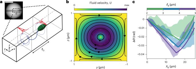
a, Sketch of E. coli swimming through a channel. Swimming E. coli exert a torque dipole on their surroundings, which stems from the counter-rotation of the cell body (clockwise when viewed from the rear) and flagella (anticlockwise). These two torques drive a hydrodynamic flow resulting in traction forces on the top wall of the channel (red arrows). The traction fields induced by each torque are offset by a distance ℓD and, thus, produce a net torque on the puck that drives the observed clockwise rotation. Inset: fluorescence microscopy image of an E. coli swimming through a channel. b, Hydrodynamic flow field from a single, clockwise-rotating rotlet near the front of the bacterium. c, Predictions of the model for bacteria of different lengths and, hence, dipole separation ℓD (solid lines) and comparison with the experimental measurements. The shaded zones represent the standard deviation of experimental measurements for four trajectories of each size of bacterium. The hydrodynamic model quantitatively captures the experimental observations. Scale bar, 10 μm. max, maximum.
To confirm this mechanism, we modelled the hydrodynamic interaction of a single E. coli cell swimming through a square microchannel of width 2W. The bacterium is assumed to be aligned with the axis of the channel, consistent with experimental observations. For analytical progress, we approximated the channel walls as infinite stationary boundaries. To leading approximation, the bacterium exerts both a force dipole and a torque dipole on the fluid around it. For a bacterium aligned with the channel axis (x direction), symmetry precludes the force dipole from driving any net torque, and we, therefore, omit it in our flow calculation. Instead, we idealize the bacterium as exerting two equal and opposite point torques (or rotlets) \(\pm {\varGamma }_{{\rm{M}}}\,\hat{{\bf{x}}}\) at locations r1,2 offset by a fixed distance ℓD along the channel axis: \({{\bf{r}}}_{1}-{{\bf{r}}}_{2}={\ell }_{{\rm{D}}}\,\hat{{\bf{x}}}\). The microscopic torque magnitude ΓM is given by the bacterial motor torque. The torque spacing, or dipole length ℓD, is expected to scale with the size of the bacterium, a point we elaborate on below.
We first analyse the effect of a single rotlet \(+{\varGamma }_{{\rm{M}}}\hat{{\bf{x}}}\) at location r1. At low Reynolds number, the fluid motion it induces inside the channel satisfies the Stokes equations,
$${\rm{\nabla }}\cdot {\bf{U}}=0,\,\,{\rm{\nabla }}\cdot \mathit{\varSigma} =-\frac{{\varGamma }_{{\rm{M}}}}{2}{\rm{\nabla }}\times [{\rm{\delta }}({\bf{r}}-{{\bf{r}}}_{1})\hat{{\bf{x}}}],$$
(1)
where U is the fluid velocity, Σ = −PI + 2μE is the Newtonian stress tensor expressed in terms of the pressure P, dynamic viscosity μ and rate-of-strain tensor \(E=\frac{1}{2}({\rm{\nabla }}U+{\rm{\nabla }}{U}^{{\rm{T}}})\), and δ(r) is the Dirac delta function. The fluid velocity is subject to the no-slip condition at the channel walls: U(x, y = ±W, z = ±W) = 0, where the x coordinate is aligned with the channel axis and the z direction is normal to the bottom substrate (Fig. 3a). By linearity of the Stokes equations, the fluid velocity depends linearly on the torque,
$${\bf{U}}({\bf{r}})=\frac{1}{8{\rm{\pi }}\mu }{{R}}({\bf{r}}-{{\bf{r}}}_{1})\cdot {\varGamma }_{{\rm{M}}}\hat{{\bf{x}}},$$
(2)
where R(r) is the Green’s function for this problem. As explained in Supplementary Information, the solution for U(r) can be obtained numerically by solving equation (1) using the boundary-element method26 (Fig. 3b). The velocity field in equation (2) exerts a traction on the channel walls. As the bottom wall is part of the fixed substrate, only viscous stresses on the top wall (z = +W) contribute to the vertical torque on the puck. There, the viscous traction is
$${\bf{t}}({\bf{r}})=-\hat{{\bf{z}}}\cdot 2\mu {{E}}({\bf{r}})=-\mu \left(\frac{{\rm{\partial }}{U}_{x}}{{\rm{\partial }}z}\hat{{\bf{x}}}+\frac{{\rm{\partial }}{U}_{y}}{{\rm{\partial }}z}\hat{{\bf{y}}}\right),\,\,\,z=+W.$$
(3)
This results in a net torque on the puck:
$${\varGamma }_{1}\hat{{\bf{z}}}={\int }_{\,z=+W}({\bf{r}}-{{\bf{r}}}_{{\rm{C}}})\times {\bf{t}}({\bf{r}}-{{\bf{r}}}_{1})\,{\rm{d}}S=-({x}_{1}-{x}_{C}){\int }_{\,z=+W}\mu \frac{{\rm{\partial }}{U}_{y}}{{\rm{\partial }}z}\,{\rm{d}}S\,\hat{{\bf{z}}}\,,$$
(4)
where rC denotes the centre of the puck. Upon inserting equation (2), the torque magnitude reduces to
$${\varGamma }_{1}=-{{\varLambda}} \left(\frac{{x}_{1}-{x}_{C}}{W}\right){\varGamma}_{{\rm{M}}},\,\,\,\,{\rm{w}}{\rm{h}}{\rm{e}}{\rm{r}}{\rm{e}}\,\,\,\,{{\varLambda}} =\frac{W}{8\pi }{\int }_{\,z=+W}\frac{{{\partial }}{R}_{{yx}}}{{{\partial }}z}\,{\rm{d}}S.$$
(5)
This expression captures the transmission of the viscous torque from the point rotlet (ΓM) to the puck (Γ1). Note that Λ is a positive dimensionless constant independent of any parameters (including W); our boundary-element calculations in an infinite square channel provide a value of Λ ≈ 0.17.
As the bacterium swims through the channel, the torque dipole resulting from the counter-rotation of the cell body and flagella produces a net torque on the puck:
$$\varGamma \hat{{\bf{z}}}={\varGamma }_{1}\hat{{\bf{z}}}+{\varGamma }_{2}\hat{{\bf{z}}}=-\mathit{\varLambda} \frac{{\ell }_{{\rm{D}}}}{W}{\varGamma }_{{\rm{M}}}\hat{{\bf{z}}}\,,$$
(6)
where ℓD = x1 − x2 is the dipole length. Notably, the torque magnitude Γ is independent of the position of the bacterium under the puck, provided that both rotlets are inside the channel; it is also independent of the orientation of the bacterium (\(+\hat{{\bf{x}}}\) or \(-\hat{{\bf{x}}}\)) along the channel axis, as observed in the experiment (Supplementary Fig. 6).
We can now describe the angular dynamics of the puck. We denote by XB(t) = Ust the instantaneous position of the bacterium inside the channel, measured from the channel entrance. Here, Us, the bacterial swim speed, is constant, as measured experimentally (Fig. 2a). If both rotlets are contained inside the channel, the torque on the puck is constant and given by equation (6), resulting in the angular velocity:
$$\frac{{\rm{d}}{\varTheta}}{{\rm{d}}t}={M}_{{\Theta }}\varGamma ,$$
(7)
where MΘ is the rotational mobility of the puck for rotation around the z axis. The value of MΘ is obtained from the Stokes–Einstein relation, MΘ = DΘ/kBT, where kB is the Boltzmann constant and T is temperature. The rotational diffusivity of the puck in a thermal bath was measured independently: \({D}_{\mathit{\varTheta} }=(6\pm 1)\times 1{0}^{-5}\,\,{\rm{r}}{\rm{a}}{{\rm{d}}}^{2}\,{{\rm{s}}}^{-1}\) (Supplementary Fig. 4). Integrating equation (7) and eliminating time using the swim speed provides the angular displacement as a function of the position XB of the bacterium in the channel:
$$\Delta {\varTheta} ({X}_{{\rm{B}}})=-{\varLambda} \frac{{\ell }_{{\rm{D}}}}{W}\frac{{M}_{{\Theta} }}{{U}_{{\rm{s}}}}{\varGamma }_{{\rm{M}}}{X}_{{\rm{B}}}.$$
(8)
This relation predicts clockwise rotation of the puck and captures the linear decrease observed in the experimental data (Fig. 2c,g). All the prefactors in equation (8) can be estimated based on experiments (Supplementary Table 1), with the exception of the dipole length ℓD. The collapse of the angular displacements upon scaling ΔΘ with cell body length in Fig. 2f points at a linear relation between ℓD and ℓB, and therefore, we posit that ℓD = αℓB. The dimensionless parameter α is the only fitting parameter in our model. By fitting equation (8) to the experimental data, we estimate α ≈ 1.5.
This simple hydrodynamic model allows us to explain the anticlockwise rotation of the puck, as observed in the second half of the down–up shape (Fig. 2c,g). As the cell body exits the channel, it ceases to exert a torque on the puck, which is now only subject to the torque Γ2 due to the rotating flagella, thus causing a change in the direction of rotation. We estimate the angular displacement beyond that point to be
$$\Delta \mathit{\varTheta} ({X}_{{\rm{B}}})= \frac{{\varLambda}}{W}\frac{{M}_{{\varTheta} }}{{U}_{{\rm{s}}}}{\varGamma }_{{\rm{M}}}\left[\frac{{X}_{{\rm{B}}}^{2}}{2}+{X}_{{\rm{B}}}({\ell }_{{\rm{B}}}-{\ell }_{{\rm{D}}}-R)+\frac{{\ell }_{{\rm{B}}}({\ell }_{{\rm{B}}}-2R)}{2}\right],$$
(9)
which predicts a reversal in the direction of rotation with a quadratic dependence on position. The hydrodynamic model provides a quantitative description of the rotation through equations (8) and (9). The rotation is controlled by either the two rotlets or a single one inside the channel. The transition is observed in the experiment as the position of reversal of the down–up shape (Fig. 2c).