
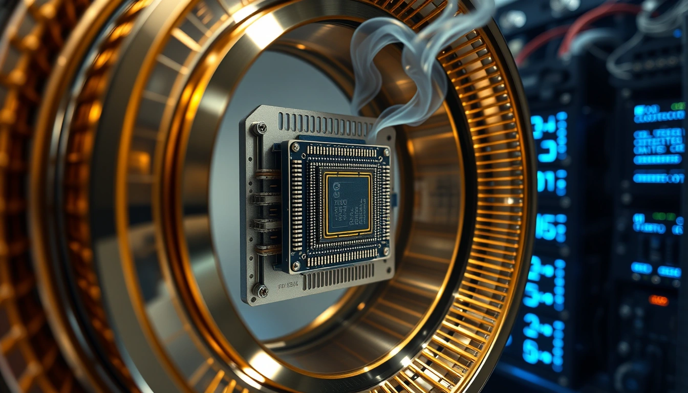
In January 2025, MIT researchers pushed a superconducting fluxonium qubit to record single-qubit gate fidelity with two newly designed control techniques. The result showed how tightly quantum accuracy is tied to the electronics and pulses that operate the qubit. For background, see our recent coverage.
How do qubit control and readout complete a computation?Control signals differ by qubit technologyThe control loop in one passHow qubit readout works after the control pulses endDispersive measurement and resonator responseDoes reading destroy a qubit?What determines qubit readout fidelity?Signal-to-noise ratio, phase noise, and synchronizationA recent readout benchmarkWhy channel count makes bandwidth and signal quality harder to manageFrequency-multiplexed qubit readoutIntegrated hardware as a concrete scaling exampleHow do calibration, latency, and feedback keep operations accurate?Qubit control calibration and latencyWhat feedback doesIntegrated vs. separate qubit control hardwareWhere separate instruments fitWhere integrated hardware helps, and where it does notPutting the signal chain togetherRelated articles
A room-temperature controller drives a cryogenic QPU, then receives and classifies the returning readout signals. Tech Insider illustration.
Industry insights, the latest tech news, and special interviews, all in the Tech Insider Newsletter.
One email a week. No spam, unsubscribe anytime.
Qubit control and readout use classical electronics to send precisely shaped, precisely timed signals that change a qubit’s state, then apply a measurement pulse and classify the returning signal. Accurate operation demands calibrated amplitude, frequency, and phase; synchronized channels; low-noise acquisition; and feedback that finishes before the quantum state loses coherence.
Superconducting hardware gives the clearest worked example of this loop, so the concrete numbers below come from that platform. The same principles govern trapped-ion systems and semiconductor spin qubits, which swap microwave tones for lasers or electrical pulses.
Google · Preferred Sources
Don’t miss new tech stories on Google
Add Tech Insider once in the Google app and our stories appear in your news suggestions.
How do qubit control and readout complete a computation?
Control prepares and changes the quantum state; readout converts the final state into classical data. A quantum processing unit cannot execute an algorithm on its own. Classical electronics translate every compiled instruction into physical signals before anything quantum happens.
Control signals differ by qubit technology
Different qubit technologies respond to different signals:
Superconducting qubits use microwave pulses and, in some architectures, flux-bias signals that tune the qubit frequency.
Trapped ions use laser pulses and magnetic fields for control, with collected photons for detection.
Semiconductor spin qubits use microwave or electrical pulses paired with charge-sensitive measurement.
For superconducting qubits, pulse frequency selects the qubit transition. Amplitude scales the rotation angle. Phase sets the rotation axis on the Bloch sphere, and duration and envelope define how the pulse evolves over time. Together, these parameters determine the implemented gate.
The generator never touches the qubit directly. Its output passes through mixers or direct-RF stages, filters, attenuators, and cabling before it reaches the cryogenic environment around the chip.
The control loop in one pass
The loop runs in a fixed order. A compiler turns each instruction into a waveform description, and the hardware generates that waveform and drives it through the radio-frequency signal chain into the cryostat. The qubit responds. The receiver digitizes and classifies that response, and a conditional operation may fire before the loop closes.
The control technique strongly affects fidelity. MIT reported in January 2025 that two new fluxonium-control methods reached 99.998% single-qubit fidelity. The team achieved this by optimizing drive pulse envelopes and operating at flux-insensitive bias points to minimize decoherence and state leakage, demonstrating how tightly quantum accuracy depends on precise control execution.
The complete signal chain: controller, radio-frequency stage, cryostat and QPU, readout resonator, analog-to-digital converter and demodulation, state classifier, and feedback path. Tech Insider illustration.
How qubit readout works after the control pulses end
Qubit readout in a superconducting circuit is indirect by design. The measurement never probes the qubit directly; it measures how the qubit shifts the response of a coupled readout resonator.
Dispersive measurement and resonator response
The readout system applies a measurement tone near the resonator frequency, detuned enough from the qubit to avoid direct excitation. The qubit state shifts the resonator’s effective frequency and phase response, a scheme called dispersive readout. The returning microwave field therefore produces a state-dependent distribution in the in-phase/quadrature, or I/Q, plane, with |0⟩ and |1⟩ centered at different locations.
The returning signal is weak, so the receiver amplifies it through low-noise gain stages before downconversion and digitization. Filtering and weighted integration then compress each record into one I/Q point, and a classifier assigns that point to |0⟩, |1⟩ or another modeled state. Single-shot readout means the assignment comes from one measurement, not an average of repeated measurements.
Does reading destroy a qubit?
Usually not, but the wording matters. Measurement collapses a superposition into an outcome tied to the measurement basis, and that backaction is fundamental physics. The physical qubit generally survives and can be reset or reused. Some measurements are destructive on particular platforms. Quantum non-demolition protocols preserve the measured observable long enough for repeated interrogation. Collapse affects the state; it does not necessarily destroy the device.
I/Q plane with clusters for |0⟩ and |1⟩ and the decision boundary between them. Tech Insider illustration.
What determines qubit readout fidelity?
Qubit readout fidelity is the probability that the measurement system assigns the correct state under a stated protocol. It is not gate fidelity, and a bare percentage means little without the state set and averaging method stated alongside it.
Signal-to-noise ratio, phase noise, and synchronization
Noise added in the receive chain and losses along the line pull the I/Q clusters toward each other until overlap causes classification errors. Phase noise is short-term instability around a signal’s carrier; it spreads phase uncertainty and can blur both rotations and demodulated readout. Clock jitter moves pulse edges and sampling instants; channel skew separates nominally simultaneous channels in time. Poor synchronization lets two operations that should share a phase reference arrive at different phases.
The table below separates four terms that hardware documentation often conflates.
Phase noise — What changes: Carrier phase over short timescales — Typical consequence: Broader rotations or smeared I/Q distributions
Timing jitter — What changes: Edge or sampling time — Typical consequence: Pulse-placement and sampling error
Channel skew — What changes: Relative timing between channels — Typical consequence: Misaligned multi-qubit control or readout
Latency — What changes: Delay through acquisition and decision processing — Typical consequence: Feedback arrives too late
A recent readout benchmark
A paper reported 140-nanosecond single-shot, frequency-multiplexed readout with 99.5% two-state assignment fidelity and no quantum-limited amplifier. The conditions are part of the result: it describes two-state discrimination under a specific hardware and pulse configuration. Assignment fidelity can be limited by imperfect state preparation, relaxation during the measurement window, resonator overlap, classifier thresholds, and leakage outside the computational basis. The figure is an engineered result, not a universal benchmark.
The paper reported 140-nanosecond single-shot, frequency-multiplexed readout with no quantum-limited amplifier. Higher noise expands each I/Q cluster and increases overlap across the decision boundary. Tech Insider illustration.
Why channel count makes bandwidth and signal quality harder to manage
Adding qubits multiplies the tones and synchronized operations a system must handle, while the physical constraints remain fixed. Available spectrum, converter bandwidth, wiring capacity, and the cryostat’s thermal budget are all limited.
Frequency-multiplexed qubit readout
Frequency-multiplexed qubit readout gives each resonator its own frequency and combines the probe tones on a shared feedline. Digital channelization then separates the returned tones. This cuts the required line count, which is why large processors lean on the technique.
The trade-offs are real. Crest factor rises. Intermodulation products appear. Crosstalk grows, and every added tone expands the calibration burden. The channel must hold all the tones inside its window at once, which raises the required instantaneous bandwidth.
Instantaneous bandwidth is the span a channel can generate or capture at one time around its configured operating point. It is not tuning range. A device may tune across many gigahertz and observe only a fraction of that spectrum at any given moment.
Integrated hardware as a concrete scaling example
A current example is Qblox’s qubit control and readout QRC module, whose official specifications list continuous 100 MHz to 10 GHz coverage and more than 800 MHz of instantaneous bandwidth per channel. The same documentation specifies frequency-multiplexed readout for eight frequencies. These figures describe three separate constraints: where a channel can tune, how much spectrum it can process at once, and how many readout tones it can separate concurrently.
Combining signal generation and acquisition in one module can reduce external mixing stages and simplify synchronization. System performance still depends on calibration and every component between the module and the qubit.
Eight readout tones inside an acquisition window wider than 800 MHz. The diagram is conceptual and not to scale. Tech Insider illustration.
How do calibration, latency, and feedback keep operations accurate?
Calibration maps each intended quantum operation onto the drive amplitudes and phases the real hardware needs, plus timing offsets and classifier thresholds. Latency then decides if a measured result can still influence the circuit before decoherence or the protocol deadline.
Qubit control calibration and latency
Calibration runs at three levels. Pulse calibration sets the drive frequency and waveform shape. Channel calibration corrects gain and offset errors, mixer imbalance, and phase misalignment. Readout calibration estimates the I/Q clusters and sets decision thresholds.
Drift never stops. Temperature swings, component aging, and slow shifts in qubit frequency force periodic recalibration on every channel.
Latency is the complete measurement-to-action interval, not just analog-to-digital conversion time. It covers signal propagation and cable delay, the acquisition chain of filtering, integration, and discrimination, and the routing and waveform launch that follow the decision.
Deterministic latency is not the same as low average latency. Quantum error correction and active reset need a predictable deadline, so a fast average with occasional long delays can still miss the protocol. Jitter adds timing variation to that latency.
What feedback does
Feedback is a conditional classical action taken in response to a measured result. Active reset, adaptive measurement, and the conditional responses inside error-correction cycles all rely on it.
Conditional branching on a controller does not deliver fault tolerance by itself. The loop must close inside the deadline with margin to spare, or the correction arrives after the state it was meant to fix.
Timing from the readout pulse through acquisition, integration, and classification to the conditional control pulse. Tech Insider illustration.
Integrated vs. separate qubit control hardware
Separate hardware splits the signal chain across distinct instruments: one box generates waveforms, another mixes, another digitizes, and another processes. Integrated hardware combines more of those functions under one timing and software architecture. Neither format is universally superior.
Where separate instruments fit
Modular instruments let a lab replace or upgrade one component at a time and validate each block independently. Reconfiguring for a new experiment is straightforward. The costs add up: more cables and clocks, more trigger paths and software interfaces, more rack space, and more calibration boundaries between boxes.
Where integrated hardware helps, and where it does not
Integrated designs shorten signal paths and centralize clocking, which can reduce trigger ambiguity and consolidate calibration. The trade-offs are real. Vendor dependence increases. Component substitution gets harder. A single chassis can concentrate failure points, and dense radio-frequency circuitry needs careful thermal design.
Cryogenic control electronics deserve separate treatment. Moving generation and acquisition closer to the QPU cuts wiring and propagation delay, but every milliwatt dissipated becomes a heat load the cryostat must absorb. Room-temperature hardware and cryogenic CMOS electronics are not equivalent choices.
Choose hardware for the system in front of you. Start with qubit type and frequency range, then simultaneous bandwidth and channel count, the feedback deadline, and the calibration workflow the team can sustain. A lab that needs component-level flexibility should weigh that requirement explicitly.
Putting the signal chain together
Qubit control and readout succeed or fail as one system. A waveform can leave the generator perfectly and still arrive mistimed or too noisy to classify; a perfect classifier cannot rescue a late decision. Map the QPU’s physical interface against frequency coverage and synchronization error. Weigh the readout method, the feedback deadline, and the calibration workload the team can sustain. Document the required channel count and timing budget before comparing controller specifications.
Related articles
 Marcus Chen
Gaming & Consumer Tech Editor
The Tech Insider Newsletter
Industry insights, the latest tech news, and special interviews, every week.
One email a week. No spam, unsubscribe anytime.